Multiple Effects in one box
|
Hi , this is my first post and wanted advice on connecting multiple Fx into one box say a metal enclosure, size about 400mm x 300mm x 100mm... should be able to get at least 10 effects in there with enough room for all the in/ out jacks and pots on the top of the panel....And then i could connect any effect to any other in any order i like using patch leads....
would i be able to run all the DC power wires which i could solder to each board and run them to a main DC connector and just use one wall wart type mains adaptor. I have searched all over web and get nothing on this, then stumbled onto this ace website. I've noticed a couple of threads were someone has put a couple into one box, but just think of the possibilities and ease of use to have all your favourite pedal effects in one box rather than using bulky pedal boards.. Sorry for long post but i would really appreciate any info or a point in the right direction plus I'm looking forward to start building some of these kits... |
|
You're going to need a very high current capacity power supply to run ten effects on one wart. Most of the pedalboard-specific ones out there will probably take it no problem but it is something you have to consider.
Sounds like an interesting project, good luck.
Through all the worry and pain we move on
|
|
I would look for a 1 amp supply. That gives you 100 mA average per effect. Most dirt box circuits use around 10 mA. Delays and reverbs use more current. Unless you've got a bunch of digital effects, you should be fine.
I recommend a regulated power supply to avoid hum. You could build the regulation into the enclosure. Use any cheap 1-2 amp, 12V DC supply, and put a small regulator circuit (a 7809 with a 10-1000uF cap from 12V to ground, a 100nF cap from 12V to ground, and a 100nF cap from 9V to ground) inside the box along with the effects circuits. Lots of us will be interested to follow your progress. Updates and pictures are welcome. |
|
In reply to this post by carpark62
@Carpark: I've done a 3-in-1 somewhat recently, details in here towards the end
http://guitar-fx-layouts.42897.x6.nabble.com/First-2-in-1-any-advice-td2618.html It's a 1790NS and pots are 9mm Alpha so it might give you some indication of space available. |
|
In reply to this post by induction
Hi thanks for all your welcome replies, I'm going to start straight away. I have already taken apart a dod thrasher, a boss wa wa , a dod stereo phaser, a behringer 8 band EQ, a behringer octave, a danelectro flanger, a danelectro distortion, a digitech stereo chorus , a digitech stereo delay. and I'm just waiting on aDigiTech HardWire Series RV-7 Reverb Pedal to arrive..
I think this should do it for now and i know some of these effects aren't groundbreaking, but i think will be able to come up with all sorts of results.. just have to make sure i wire it all up right and i will put pictures up so you can all see. I have a couple of various power adaptors i can use, will try a 1.2 Amp one first but also got a 3.6 amp if needed. @ induction could u be a bit more specific on this power regulator, say a link of a build i could follow would be great, and even though i'm using a metal enclosure do i have to earth it even though i think i can build this without any of the circuits , sockets touching it. If i can pull this off then i am going to build another similar system using just the kits of this site!! |
|
Here's a vero of a simple regulator circuit:
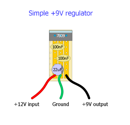 The 7809 regulator looks like this: 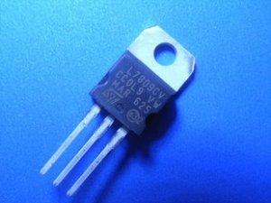 If you're powering 10 circuits I recommend using a heat sink on the regulator. Apply some heat sink compound to the back of the metal tab and attach a heat sink with a small nut and bolt. Instead of a proper heat sink, you could bolt it directly to the enclosure or a metal washer or something (either way, you still need the thermal compound, that bit is important). FYI, the metal tab connects internally to the ground lead. The regulator requires a few extra volts for proper operation, so you will need to use a 12V adapter as input. Powering a 9V regulator with a 9V adapter will sometimes work intermittently, but will generate audio artifacts in many circuits. The 12V adapter can be any cheap, old leftover you have hanging around, just watch the polarity. If you connect the leads wrong, you might let the magic smoke out. Yes, you should definitely ground the enclosure. With high voltages, it's essential for safety. With 9V circuits, it's not that big of a deal, safety-wise, but the grounded enclosure acts as a Faraday cage, preventing stray magnetic fields (from air conditioners, fluorescent lights, ghosts, etc.) from inducing electric current in your circuit wires. This will make your circuits much quieter and less susceptible to hum, noise, and interference. I'm not familiar with all of the circuits you listed, but if any of them are digital, you may need a special adapter for them. Sometimes they need a different voltage, and sometimes they need AC power instead of DC. Even if they take 9V DC, they may have excessive current requirements, so you should research them thoroughly with regard to how much current they require. In my experience, analog and digital devices should not share power supplies because the digitial devices induce noise in the analog circuits. Test them thoroughly before you commit them to the box. If necessary, you can always use the regulated supply for all of the analog circuits, and have separate jacks for the digital ones. I recommend using the original PSU's for any digital devices. Don't skip the regulator. You can get by without it, but it's impossible to overstate how useful it is for hum reduction. It makes all the difference in the world. Some circuits are so noisy with unregulated power that they are completely unusable. |
|
Thank you very much for your detailed Info on all this, its given me a lot to way up and think about, i think i can manage the regulator no probs, less hum the better, but may need to be a burden with the ground, should i use the poz or neg as some effects like to use same
So this is why i was not going to use the enclosure to ''not'' do either...earth..etc..as each effect will act independent of each other until patched with gables, just as if on a pedal board!! Or is this where problems start ? as in even having to be careful how you wire a pedal board. this bit is new to me....A bit slow ha, But yes i was hoping to patch them altogether with the same power supply, but yes some of these effects are digital, like the berhinger and the danefecto pedals... surely these dumb ass pedals can be powered together? but already know i have a lot to learn and want to!! Thanks Very Much louis. |
|
Positive and negative ground circuits can share ground. They will anyway since your guitar cable has a ground connection. It should be no problem to ground the chassis regardless of the polarity of the pedals. Just don't mix the rail voltages if they aren't the same. (IE don't connect +9V to -9V, obviously.) Positive ground analog circuits can also be daisy chained with negative ground circuits if you put a charge pump between the PSU and the positive ground power rail.
It's easy enough to check whether your digital pedals can share a power supply with each other, or even with your analog pedals. Just daisy chain them (assuming they are all the same voltage and polarity) and see if the analog pedals get noisy, or if the digital pedals function at all. Digital circuits tend to produce noise in the power line, and to use a lot of current. I'd be wary of two digital pedals sharing a PSU unless it has the combined current capacity of both of them individually. In other words, if you have two digital pedals with 9V negative ground adapters with 100 mA ratings, then you could probably use a single adapter with a 200 mA rating. If they don't get enough current they won't run, or they'll cut in and out. So assuming all of your pedals use 9V DC, you could probably use one PSU for analog and another one for digital. You'd want to keep them physically distant from each other on the chassis to minimize digital noise in the analog ground. |
|
Just to be clear, the difference between positive and negative ground circuits isn't the ground, it's the voltage of the power rail. Positive ground circuits use -9V and 0V, negative ground circuits use +9V and 0V. So the grounds are compatible, the rails are not.
|
|
Thanks for help induction, i'm using a regulated power supply 3600 mA, is it still wise to use the regulator circuit? I have decided to not use the case as an earth to less complicate things. I've noticed the pos and neg wires i have going to the rails build up heat so i was wondering if the wire i've used is to thin or could it be the high amp power supply i'm using..
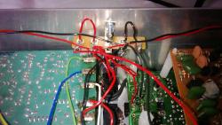 I'm running out of room in the enclosure now but have one more distortion effects to put in.. 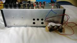 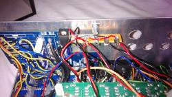 Its getting a bit crumbed now... 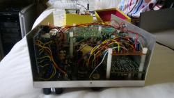 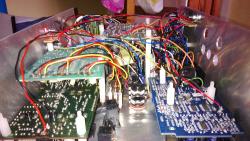 But still hoping to squeeze in a DigiTech HardWire Series RV-7 Reverb Pedal i have on order.. 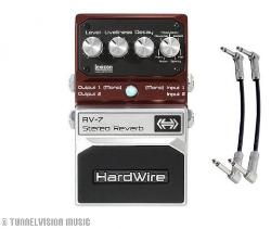 This reverb should finnish it off and i can get twiddling ha.. 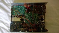 As you can see its not the best attempt and looks a bit cumber sum!! to look at.. 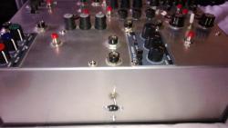 But my main objective was to mangle sounds by patching effects in any order i like and just see what comes out of it... 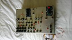 I should probably mention that i don't play guitar and will use this with my synths and can have it patched into my daw so even soft synth plugins can run through it... It could do with a paint job, but not sure i've got the heart to take it all apart and put it back together lol.. |
|
If your power supply is regulated (I'm assuming +9V DC) and quiet, then you don't need a separate regulator circuit. It wouldn't work anyway, since you need +11V or more to run a +9V regulator. If you don't get hum from your circuits, all's well.
The 3600 mA current rating tells you the maximum amount of current the supply can deliver, but it will only deliver what the circuits consume. 3600 mA might be overkill (or not, I don't know what your digital pedals consume), but it won't hurt anything. If your circuits consume 1 A, then there is no practical difference between a 1.5 A supply and a 3.6 A supply. If your power leads are heating up, then they are delivering more current than they can safely handle, and eventually they will fail. Replace the ones that get hot with thicker wire. In this case, it's a good idea to feed each circuit with a separate wire directly from the adapter so the current gets spread out over multiple wires. Any wire that carries current for multiple effects will get hotter than one that feeds only one circuit. This is especially important for the digital effects, since they consume the most current (by a large margin). You could probably daisy chain the power to the analog circuits from one to the next without a problem, but the digital ones should each get a wire directly from the adapter. The project looks great, by the way. Well done. |
«
Return to Open Chat
|
1 view|%1 views
| Free forum by Nabble | Edit this page |

