|
This post was updated on .
hey there,
I felt brave enough yesterday to build a Mutron Phasor II clone, it works and sounds great. I think I can fit it in a 1590BB (notice the "I think" part) I'd like to try different things with it (maybe try another LFO, add stages and/or a switch to select between the number of stages, have a PCB manufactured, etc.) BUT all I can find is a very bad resolution schematic... does anybody have a proper schematic? that would be awesome, thanks in advance |
|
Quick glance at Madbeans Nu Tron 2 seems to match Marks layout
http://s999.photobucket.com/user/njkmonty/media/ScreenHunter_04Sep231955_zps792f20f3.jpg.html |
|
That's perfect, indeed! Thank you!
|
|
I noticed some ticking from the clock (including bleed in bypass) and read everything I could about suppressing ticking, but there's something that bothers me, here.
I'm not trying to be an ass and am REALLY grateful for this layout in particular and all the great things available on this site, but I have a question about this layout: Aren't the LFO opamps split across the 2 tL082 (in my case) bottom right of the layout? and the bottom middle one seems "shared" with an input buffer. It appears to me that the second opamp of this chip is generating a square waveform. Wouldn't it be the cause of ticking (or increase ticking)? I'm working on a PCB layout for it, hope I can work this out |
|
I got a board from a guy on the Madbean forum who had created a PCB layout that could fit into a 1590B. Incredibly tight component wise. But the sound........
|
|
Please report, when you've finished building it!
I'm interesting in how is the ticking on it! I had overlooked something quite basic: my enclosure wasn't grounded... the ticking (though still present) is totally acceptable, but hey, whatever i can do to lower it some more... |
|
Administrator
|
I've built both the stripboard layout here and the PCB that Muazdin referred to
My stripboard build ticks, including in the bypass signal, and I have pretty much given up on fixing it. The PCB build has no tick or noise issues at all |
|
thanks for your report! I see 2 major differences between the 2 circuits: the PCB version has one dual opamp package only for LFO duties and there's only one LED (against 3)...
|
|
Administrator
|
No I didn't do the layout with any specific opamp order in mind, I just used the most appropriate opamp and channel to allow the layout to flow as compactly as possible. As such the LFO has been split over two separate opamps. I tried to mitigate that by adding the extra diode to the supply for both LFO opamps to try to isolate them somewhat from the other opamps.
I think with any LFO effect there is always a chance that you will get some ticking, and I'm sure it was Javi who built this on vero and on PCB and said they both had identical amounts of noise, and some people have built this and got no noise at all. LFO ticking has always been a crap shoot for me no matter how much protection you try to add to prevent it. |
|
Administrator
|
I think Mark is right of course. It's not as cut and dry as stripboard bad PCB good. I believe there were some members here who did the stripboard build with no issues.
For what it's worth, I'm still amazed at how nicely Mark made the stripboard layout. At the time that it was drawn, I wasn't aware of any PCBs available to us DIYers for this circuit. Now that we have more options, the PCB makes more sense because you don't have to do links and cuts, and the size is much smaller. I think the PCB cost like $7 each. I don't know how many hours it took me to do the links and cuts on the stripboard build, but I know that I value the time it took greater than $7 |
|
Administrator
|
Yes, although I will build this (haven't yet), my preference would be PCBs for pretty much anything that won't fit in a 1590B on vero
![]() I love vero (obviously) but for me it excels for those single or maybe dual opamp overdrive or distortion pedals, and fuzzes which I would never dream of buying a PCB for. |
|
Administrator
|
I really liked the PCB from Kygull at madbean, Mark.
Here's a photo of my build. You can use 1/8W resistors to lay them flat of course. I used all components from Tayda (including diffused yellow LED and their LDRs) and my build sounds fantastic with no noise at all. I've listened really carefully, with and without other pedals and I can't get any ticking out of this. If I turn the feedback and depth all the way up I can hear it very very quietly sweeping, but other than that there is no noise.
|
|
Once again, lvlark, it was more a question I asked than criticism, I know close to nothing about electronics :D
I would have NEVER built it if you hadn't provided a layout, so thanks again for that. 
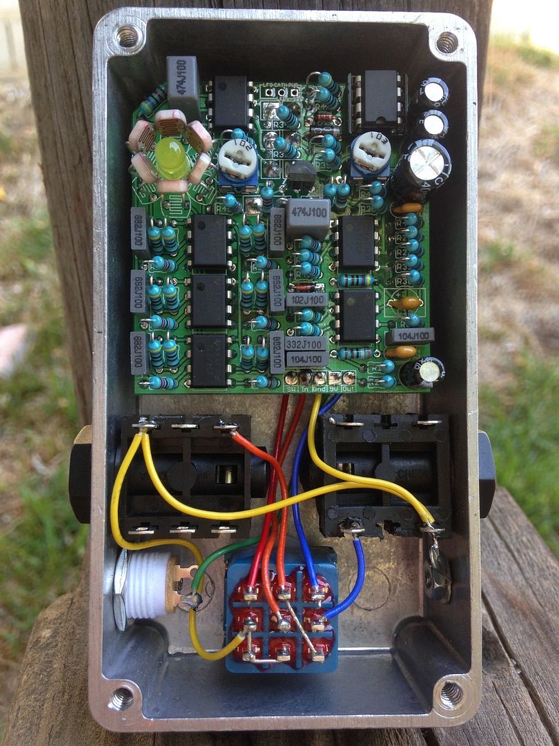
I'm just working on a PCB layout and was trying to figure out how to get the best of the circuit. As I said previously, grounding the enclosure (duh!) reduced the ticking to an acceptable level for me (but the bleed is still here), so I was wondering about this opamp stuff. Travis, thanks for the picture, I was thinking about another layout I had seen previously (with a daughterboard for the LED/LDRs) when you mentioned your 1590B build. This one is amazing! 
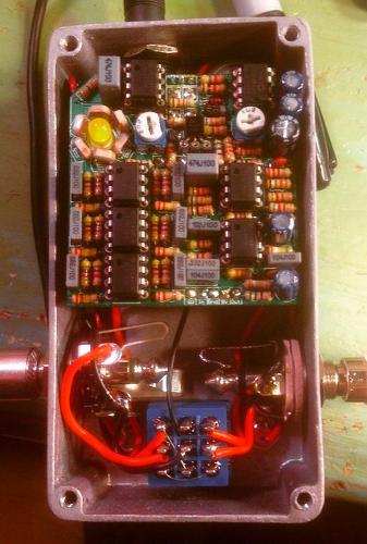
I like the resistors between the pot lugs, hehe! 
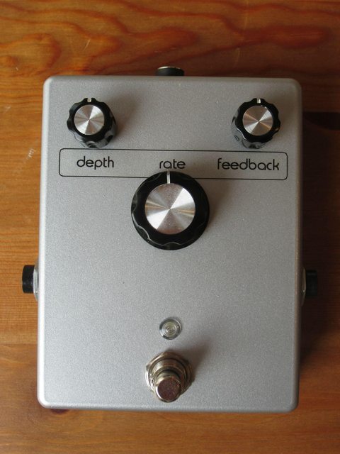
here's a pic of mine:
|
|
+1 on the krypton board from kgull on madbean. Sounds awesome and no ticking on mine. I did however try to do a little mad science... I made a daughter board for the led and ldr because I wanted to try to switch in and out stages and possibly have a manual sweep to control the led... It looked like an LDR spider... it also was unusable as it introduced a ton of ticking in the signal. I don't think it takes much for the ticking to get into the signal but the stock pcb is awesome, I even added a 4pdt switch with 4 different cap values for two different sweeps.
|
|
Administrator
|
I third the krypton. I've got mine build, just not boxed, as I just designed the enclosure before I left for vacation. I made mine with 1/8 watts because I'm a little anal about the resistors laying down completely on such a close board. As soon as I get home in going to etch, paint, and drill the enclosure so I can box it, then obviously post some pics. Next up will be making a bi-phase.
|
|
In reply to this post by Luke51411
If anyone is still interested in a krypton board, kgull still has a few. Contact him on the Madbean board.
|
|
+4 for Kgull's Krypton PCB, no ticking with mine and very true to my original. I got my 1/4 watt resistors to lay down flat - tight squeeze but doable.
![]()
|
| Free forum by Nabble | Edit this page |
