Newbie question
123
123
|
This post was updated on .
Well, I'm even more confused than before. I have no idea how to hook up the two diagrams together. The diagram I posted has wires with no termination, but the off board wiring has all wires terminated, so where do the non terminated wires go?
I see where my first error was, thinking the toggle switch was the foot switch, but the off board wiring doesn't show where the input and output wiring from the original circuit terminate. It looks like the drawing from gaussmarkov makes more sense than the one from this site. |
|
Administrator
|
Check the links I posted, it will help and explain all the build process. Basically think about it like this
 And again, I would start with something simpler then what you've ready planned. |
|
This post was updated on .
Ok, I see where I have made my mistakes. But i like the gaussmarkov diagram a lot better than the one on this site for simplicity. But what are the pros and cons of each. They are similar but different.
|
|
In reply to this post by knight_yyz
Just try to see the Circuit and offboard wiring as 2 complete separate things.
The only part that combines them are the blue wire from the circuit that says 'to output' and the green wire that say 'to input'. These wires connect to the switch (where it says output and input). Other than that, none of the signal wires from the circuit wil be connected to anything other. (The power 9v and ground will be connected too ofcourse, but that's it). Just see the offboard wiring as the main pedal/thing. The switch just gives it a little detour. The guitarsignal goes into the switch, then it goes through the green wire into the circuit (marked as input on the vero) and comes back through the blue wire (marked as output) in the switch. After that the signal goes from the switch back out of the pedal. That's what the switch does, it gives the signal a detour through the circuit and is on it's way after that. If you hit the switch, the detour is cancelled, and the signal just goes through the switch. You have an unaffected signal then. If you picture that, it's much easier to see where the circuit comes into the signal of the offboard wiring. It's just connected in the signal by 2 wires. And that's with almost every vero you'll find. The rest of the the connections to the jacks, led etc is all done outside of the circuit board. |
|
Administrator
|
In reply to this post by knight_yyz
No real difference. There's many ways to do offboard wiring.
|
|
On an AC circuit we would ground to the box. Do we do that as well for the stompboxes?
|
|
Your input and output are connected to the box. So grounding there equals grounding to the box. If it's the average aluminum.
|
|
Ok, I was wondering about that. I don't have all the parts in my hand, but I am going to start this tonight. Well, I'm going to cut the board to size and maybe make the cuts and add the jumpers.
I was able to grab 10 vero boards and most of the resisitors and caps from work, so hopefully i can get something accomplished tonight. 24 gauge wiring? |
|
In reply to this post by knight_yyz
"Ok, I see where I have made my mistakes. But i like the gaussmarkov diagram a lot better than the one on this site for simplicity. But what are the pros and cons of each. They are similar but different."
So if you like the Gaussmarkov method better, use that, but don't just look at the diagram. It's crucial that you read the whole article. Read it several times, digest it, and you will understand it. Here's the link again: http://gaussmarkov.net/wordpress/thoughts/wiring-up-a-1590b/ This is not building Airfix model aeroplanes, it's electronics, and you are going to have to learn some theory, alongside your building. Pros and cons? Again look for yourself - there is masses of info available. Type 3pdt wiring into Google and read what comes up. This is the very first hit: http://www.diystompboxes.com/smfforum/index.php?topic=110805.0 Gaining the background knowledge as you go is vital - you are going to be screwed without it. If you don't understand what's going on, and why, you will be completely unable to sort out problems when they occur - and they will occur very frequently. It happens to all of us, and we have all been in your shoes. EDIT: 24 AWG wire is good, but whatever you have that fits in the vero holes will do. |
|
Administrator
|
In reply to this post by knight_yyz
The sleeve of the jack is grounded which contacts the enclosure
|
|
Administrator
|
Every layout on here has an input and an output wire shown. Sometimes the input goes to a pot before the board, sometimes the output comes from a volume pot rather than directly from the board, as is the case with the Mastotron layout.
So all you need to remember is that the input and output wires are the things that need to go back to the main stomp switch. Take the green Input wire from the Relax/Pull pot, and the blue Output wire from the Output pot, take them back to the stomp switch, and do the rest of the stomp switch wiring as per the Offboard page. Stomp switch wiring is never something I would include in every layout because it would make them much more complicated than they needed for a function than is repeated in every build and so can be accomplished with a single offboard wiring page covering all layouts (except the ones with built in buffered bypass but that is always explained on the effect layout page). |
|
This post was updated on .
Thanks guys, I get it now. I'm sure it's happened to a lot of us. You google something, then find 20 conflicting pages about the same subject. Your brain goes numb and suddenly nothing is sinking in. While taking my dog for a walk it dawned on me how it all goes together.
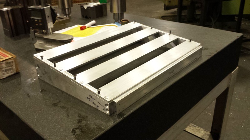
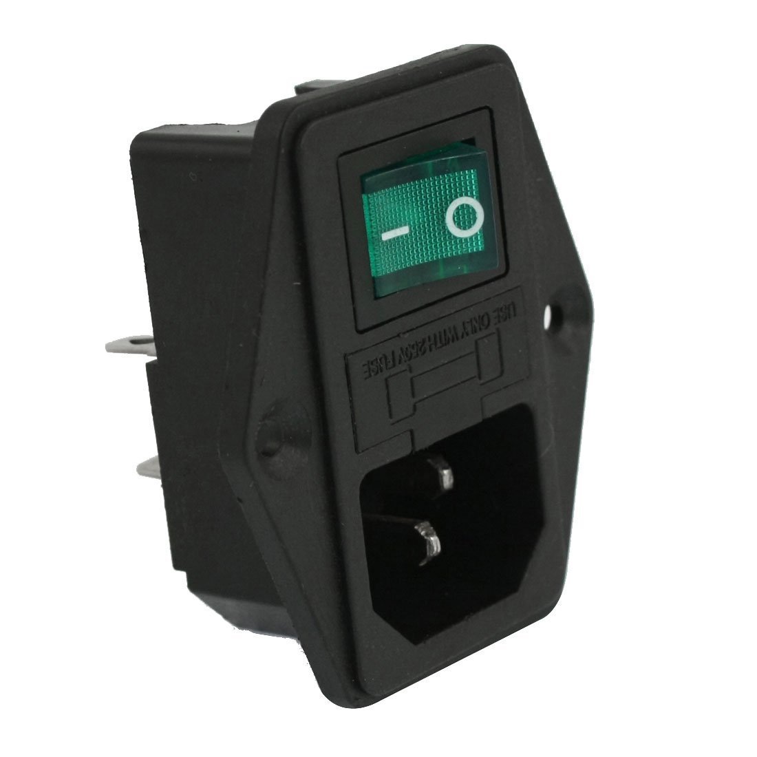
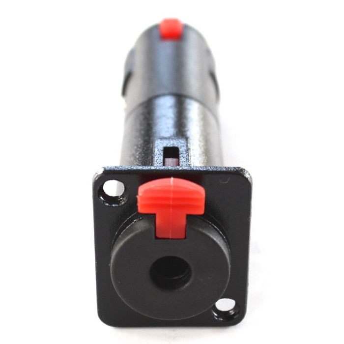
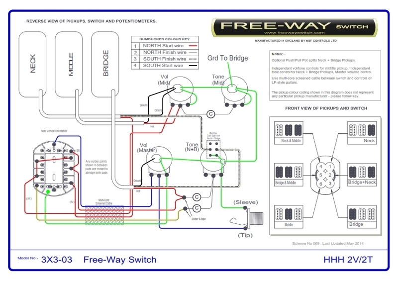
This is not my first time using a soldering iron. I have installed piggy back ECU's on several cars rewuiring splicing and tapping uof upwards 60 wires sometimes. I have converted every bulb in my car to LED using lm317's as current limiters. I'm a tool and diemaker by trade, but because of the environment I work in, I also dabble in electrical stuff, especially while troubleshooting our 2 million Euro CNC machines. Here's something I'm working on right now. My 18x12 pedal board. On off switch for the power supply and the blackbird solderless jacks...    And this is how my Black Beauty is wired...  |
|
I'm not sure how to post actual pictures in this forum, every other forum I have been on uses the [img][/img] method from photobucket.
What am i doing wrong here? |
|
When you log in to send a reply to a post, look just above where you are typing your message - there is a "insert image" tab. Click it, and you can either upload a image from your computer, or copy and paste in a web address.
I'm a tool and die maker too! |
|
Administrator
|
damn it beaker, we've know each other for how many years through the forum and i never knew that about you. i could have used someone with you skills for some crazy ideas i've had.
|
|
In reply to this post by Beaker
Thanks for that. First forum I've ever been on that allows direct upload.
|
|
That's a sweet pedal board. Aluminum?? I want to build an new analog pedal board someday - something small, modular, and light weight for gigging.
|
|
Makerbeam / Openbeam is your friend here. You could easily make an awesome fully modular and adjustable pedal board using the stuff.
And with almost no drilling or cutting involved! |
|
Administrator
|
In reply to this post by knight_yyz
Knight - it seems like you have some relevant past experience which is great.
Do you understand how a switch works? That will be very helpful for you understanding the offboard wiring. It's extremely simple if you understand how the switch works |
|
This post was updated on .
The pedal board is aluminum and weighs about 5 pounds I think. Made from scrap so it didn't cost me anything. In fact I was making about 50 an hour while I made it. LOL, I was working overtime on a slow shift so I made some calculations for the angle and where the slats would go. I added a bunch of holes for weight reduction. All the pedals going on there are, the hotone tuner pedal, the Timmy, joyo compression, joyo delay and joyo chous T Rex chameleon power supply. And eventually this clone
|
«
Return to Open Chat
|
1 view|%1 views
| Free forum by Nabble | Edit this page |

