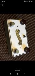
Nocturne Junior Barnyard Preamp
12
12
|
This post was updated on .
Hello.
I would love to build one of those although i know it might be hard to trace the exact parts, however, it would be nice to have the schematic or layout that i can try out various parts and see what sounds i like the most. Any info on it? From what i heard its the preamp of an Gibson EH-150 but with fets instead of the tubes. Much appreciated!!!  Best, Baouftou |
|
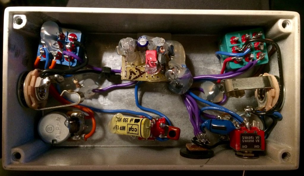
I don't know the pedal, but I found a gutshot image in this page:
https://www.tdpri.com/threads/1940s-tone-pedal-or-eq.642975/page-7 Not a great help, but we can search something more.
I build pedals
|
|
Hey thanks for the reply. It did give a bit more light as to what it is. It seems extraordinarily simple.

|
|
Yes, indeed.
It have to be just a jfet preamp, basically. But the schematic...
I build pedals
|
|
This post was updated on .
On their website it says it contains among various capacitors, a fet, and a soviet germanium transistor. So can it be a simple jfet preamp with a germanium overdrive of some sort? Do you know anything that might get close to it, if tuned properly? From what i understand the mild overdrive in sound happens more in the mid-low range freq. That could be dialed in with certain filtering, right?
What parts do you see on the gutshot? Ps: There is also this JJ-150 pedal which does a similar job i think. It is said to imitate the sound of an EH-150. https://combsguitars.com/jj150 |
Diode, not transistor. It's most likely some variation on a common source amplifier, much like a fetzer valve, an Echoplex preamp, a JHS Minibomb (aka Escobedo Duende JFET), a Tillman preamp, etc. The voicing of the circuit is going to depend on the filtering and the clipping, and I can't comment on those without ever having used the circuit. But you could compare the above circuits, listen to samples on the internet, and start experimenting on the breadboard. |
|
Thank you. Thats what i thought, and i will give it a try. But take a closer look. There is a germanium transistor on the board on the top left that is covered with plastic spread, right?. Of course there is also a diode yes.
|
Looks like an eloctrolytic capacitor to me. I only see one transistor on the board. But I could be wrong. But I don't know anything about the pedal other than what I can see in the picture and what's on the website:
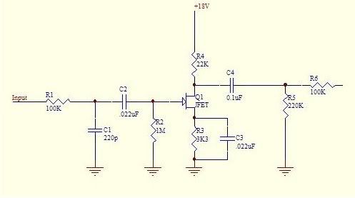
The topography of a single jfet preamp has only a few variations and clipping options, and there's not a lot of components on that board, so you can probably start with something like this for the circuit:  But it's the component values that matter, and you'll have to figure those out yourself. The Body and Depth switches could be input and output caps, and the channel switching could be an alternative source resistor or capacitor to modify the gain and/or EQ. My best guess for the diodes is asymmetric anti-parallel hard clippers to ground after the output cap, possibly with a softening resistor between the cap and the diodes. The breadboard is your friend here. This is all just guesswork based on the website and photo. Let me know if any of it is unclear. |
|
Oh man, thanks, ive been reading the text on their website wrong. It is quite tricky to figure out the values, but i would like to try. It is very clear, and good to know now that there is no such thing as a second transistor on this thing. Thanks!!
|
|
Offical page https://www.thenocturnebrain.com/products/the-jr-barnyard
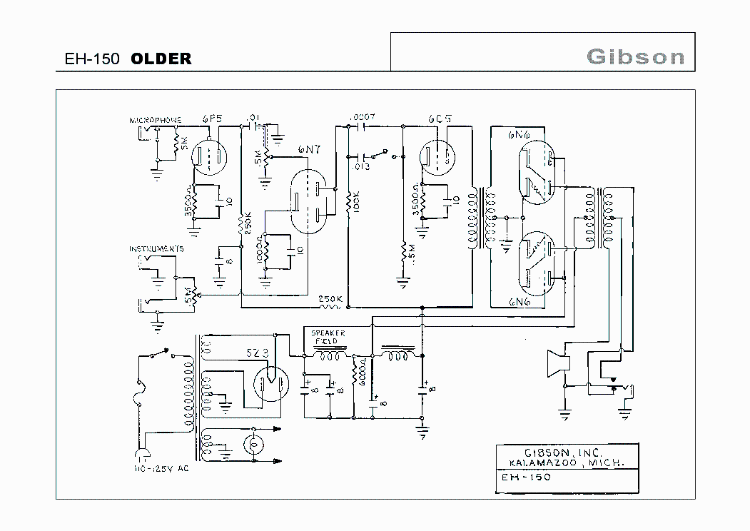
I'll do some speculation about the circuit. «This FET based preamp uses a hand selected/spec'd NOS Motorola transistor». If this pedal has just one transistor, the black one, so this pedal is not an exact copy of the preamp of the Gibson amp, but just a simple jfet boost/preamp with clipping diodes. I could wrong, but I say that it has two transistors and in the top left part of the board there's the NOS transistor, a "metal can type", and we can see how it's completely covered by that transparent plastic to keep the secret. So if the transistors are at least two, the schematic could be close to this EH150 preamp (look just at the two first tube 6F5 and 6N7):  The Grits Gain pot is the Gain control in the EH-150 schematic 0.5M pot (500k), and it should cut the volume, too, if it's exactly the same. The Volume pot probably a Volume Master (10k? 100k?) at the and of the circuit. «It has a Body depth switch (deep & Flat) and Bright switch [...]. it just flat out brings you into the front of mix with reedy vintage warmth and definition [...]». This didn't say too much about those swtch, but we can see even a switch in the end of the preamp schematic to cut low end. Maybe is the Bright/Wooly switch, the one on the upper side of the pedal in the gutshot. It adds that blue cap. The other switch swaps two caps: a big yellow and a small red caps. The value are covered. That should be a Bass/Guitar mode. It can be done replacing the original cap before the Gain pot with another bigger pot to cut less low and and allow the use of the pedal with a bass. Or change one of the bypass cap connected to the one of transistors, I assume the first one, with a larger cap, again to cut les bass. But I said the bypass caps are placed on the board and they should be electrolytic (10uF). The Grits On/Off Switch replace the dual input. It make, probably, the same thing of the EH-150 amp: bypass the first stage, that is the gain stage, and it goes directly in the second stage, for a cleaner sound. «a mix of imported Soviet germanium & Fairchild silicon diodes». I see something in the top right part of the board. Placed vertically those could be a transparent diode (germanium) and a black diode (silicon like 1N400X). We don't know how that are used, but it probably as hard clipping. Without those diodes probably when the Grit pot mode is off the pedals would sound very clean. «I added a second channel that blends in the hotter mic channel of the EH185 to it so I could dial in more texture and finger tone for my vintage style big bobbin single coil guitars. (thats the stomp switch on the left) too boot!». The new V2 version (with smd components) doesn't have the Grit switch, but a pot to blend the two channels. This version has just two knobs, so I assume the Gain pot is missing and just set at max. I think the bland of the two channels could be done in a pair or different ways. I don't know if this board has one, but an electrolytic cap as power filter it's a good idea if you have to use with a PSU. What do you think?
I build pedals
|
|
I think i agree with you. I am also seeing a germanium metal can transistor on the top left corner on the board. He indeed doesnt say it on the website but i do see it!!! Im actually in contact with a guy who owns one of those and he will hopefully send me another gutshot for us to get a better look at. Now they market it as being the pre stage of the EH-150 and it does strike me weird if its not. On the other hand i can understand that you can get overdrive in many ways so he might have just made something up and said it came from the EH-150 haha. Would it be possible to draw the preamp of EH-150 and simply swap out the tubes with a J201 and a Soviet Germanium Transistor?
|
|
There's a pair of thing.
I think it's possibile to emulate the tube preamp with jfet, any kind of equivalent jfet, as other thing like that: JCM800, Dual Rectifier... the simple Fetzer Valve, it's the first stage of the Fender. But. I not sure if this pedal do exactly the same thing, maybe it's not the same schematic of the amp. For example I can't see any resistor, and that's weird in any case! And maybe some caps is missing if you compare it with the original amp schematic. We wait for other gutshot pictures!
I build pedals
|
|
I think i see two resistors on the board. I think he mounts them vertically. One above the glass diode and another on the bottom right corner. Eh?
Also looks like there might be something hidden on the pot on the left. Omg he puts goo everywhere ..... Yikes . |
|
I can see something blue where you said.
There's just one electrolytic cap, when I expect at least two, the two 10uF from the amp schematic. I'm not sure about the plastic on the pot, or on the bypass footswitch, some parts there? Stop. I wait other pictures to clarify.
I build pedals
|
|
There just doesn't appear to be enough resistors on the board to support a 2-stage circuit. And there's plenty of room for them. Looks like a very simple circuit.
|
|
So he has the newer version which is also clearer to read.
Here are some photos and a video he sent me.    https://streamable.com/3l016s Doesnt look like there are hidden parts on the other side of the board. Also doesnt look like there is a second transistor.... Can you guyz see the traces even? |
|
Ok, one transistor. Probably that thing I thought, we thought, it was a metal can old transistor was maybe a cap? Maybe the previous version was different? Where were all those resistors?!
It will be nice if that guy could read the label on the transistors and the caps. Q1: Unknown. Pot Grit: ? Pot Volume: ? C1: Red Wima ? C2: Electrolytic cap ? C3: (6800J). Maybe this kind of caps are rather small, so it could be 6800pF (6.8nF) C4: Monoholityc cercamic cap ? C5-ALT: 0.0022k (2.2nF) C6-ALT: 0.047k (47nF). It's updown, and the just half label is visbilbe. C7: Silver cap ? Glass red diodes: 1N4148 (or 1N914) Glass clear diodes: I have some russian germanium D9E that looks like that. Black diode: 1N400X. The upper footswitch si the Boost, the downer one is the bypass. The upper toggle switch is Guitar/Bass, the downer one Bright/Wooly. I have to do some effort to find the resistors value. I think on the footswitch board we can find the LED resistors. On the Grit Footswitch there's a second resistors, it should be the mod, maybe setting a fixed resistor to replace the pot.
I build pedals
|
|
I think you preety much summed it up. That electro cap is prolly filter to ground 100uf? I asked the guy if he can read the parts. At least the transistor. Lets see, but i dont think he is in any way related to this, might take him a while. He is a guy i found owning one on instagram. But now the question is what would the wiring be? Cuz even without the exact cap values we can go near the original.
|
|
In reply to this post by fx-fidden
The Grit switch also possibly switches the clipping diodes into/out of the circuit. |
|
Looking at some video I think the second footswitch isn't a gain mode control that add distortion, but a boost with its control pot, the Grit pot. You can include or exclude it. That pot adds gain/distortion, and a bit of volume I think.
(The V2, the one without the boost footswitch and the Blend pot, I assume it has just the Grit control, and for both the versions the Grit pot at zero corresponds to the boost off). About the diodes... I'm not sure what they do. How you see those diodes as hard clipping in the end of the circuit before the Volume pot? Maybe. But I never tried it, and I don't know how much distortion could give to the sound. Too much? The pedal can still sound almost clean with the boost off. Is it possible a jfet boost with soft clipping diodes, a sort of clipping stage of the Bug Muff but jfet? I'd say the Bass/Guitar switch changes the input (or bypass cap, C1, because is the cap 1, could be the input cap). And the Bright/Wooly switch add a cap (the ceramic one?) to the ground in the end of the circuit to tame treble. The only one electrolytic cap should be the filter. It's very hard that a pedal doesn't have one. And the 1N4001 goes to the ground (or in line from the 9v) as polarity protection. Can somebody is good enough to find the resistors value just looking the images/video?
I build pedals
|
«
Return to Requests
|
1 view|%1 views
| Free forum by Nabble | Edit this page |

