Omitting Potentiometers...(replacing w/ trims/resistors)

classic Classic list List threaded Threaded
25 messages Options
12
Reply | Threaded
Open this post in threaded view
|

Omitting Potentiometers...(replacing w/ trims/resistors)

LettucePrey
If I want to leave the Damp knob off the following build, how do I go about doing so?

Reply | Threaded
Open this post in threaded view
|

Re: Omitting Potentiometers...(replacing w/ trims/resistors)

induction
Do you want it at max brightness, min brightness or somewhere in between?

I find the the damp control to be extremely useful, by the way.
Reply | Threaded
Open this post in threaded view
|

Re: Omitting Potentiometers...(replacing w/ trims/resistors)

alltrax74
Which brick are you using ?
The damp control on mine with the long decay brick makes absolutely no difference from CCW to CW
Reply | Threaded
Open this post in threaded view
|

Re: Omitting Potentiometers...(replacing w/ trims/resistors)

induction
I tried it with a medium brick, but I don't think that should affect the damp control. If it's not working on your build, there's likely a problem (bad pot, solder bridge, etc.). The response to the damp control is pretty dramatic.
Reply | Threaded
Open this post in threaded view
|

Re: Omitting Potentiometers...(replacing w/ trims/resistors)

alltrax74
Well actually  i built 3 of them with the long decay and they all beahave the same : great sounding reverb but with totally ineffective damp control
Reply | Threaded
Open this post in threaded view
|

Re: Omitting Potentiometers...(replacing w/ trims/resistors)

LettucePrey
I have the same exact problem as alltrax (as well as many others who have built this). The damp does nothing. I used the long decay brick. This is actually the reason why I made the thread to remove the pot from the circuit.

I've built it twice now and the damp doesn't change the sound.

Reply | Threaded
Open this post in threaded view
|

Re: Omitting Potentiometers...(replacing w/ trims/resistors)

induction
Interesting. Maybe it does have to do with the long brick then. I breadboarded the original version (not the Heavenwithin modded one) with a medium brick and the damp pot works well. In any case, if you just don't attach the damp pot, it should work fine. Alternately, you can put a 10k resistor between BLT5 and Rev 3, to be more true to the app note. I doubt you'll hear a difference, but if you do, you'll probably have to point-to-point the resistor, since there's not much room on the board for it.

It's a shame though. The damp pot is pretty useful. If you're interested, you might try leaving the damp pot in and disconnecting BLT6 to and see if that helps at all. The brick works fine with only one output, in my experience. This design uses both brick outputs, but only one output sees the tone control. If you disconnect the other brick output, the tone control might be more effective.
Reply | Threaded
Open this post in threaded view
|

Re: Omitting Potentiometers...(replacing w/ trims/resistors)

LettucePrey
i'll have to try to build one with the medium decay brick.

So in any build, I can replace a pot with a resitor of the same value (ex: 10K pot= 10k resistor) and that tonal variance will just be full on all the time?
Reply | Threaded
Open this post in threaded view
|

Re: Omitting Potentiometers...(replacing w/ trims/resistors)

alltrax74
That's for a pot used as a variable resistor (only 2 lugs connected).
Here the 3 lugs are connected, so you need 2 resistors, 1 between lug 1 & 2, the other between lug 2&3
It's a 10k pot so for exemple you could use 2 5k resistors, that would be the same as having the pot set at noon
Reply | Threaded
Open this post in threaded view
|

Re: Omitting Potentiometers...(replacing w/ trims/resistors)

induction
In reply to this post by LettucePrey
Mostly. There may be some cases where it won't work, but i can't think of any right now.

For more options, we can consider the ways that pots are generally used:

1. Voltage dividers. Usually lug 3 goes to incoming signal, lug 1 to ground or Vr, lug 2 to outgoing signal. Replace the pot with a resistor and take the output from where lug 3 used to be (so the incoming signal and outgoing signal are tied together. This will behave like a pot on max. If you tie the outgoing signal to where lug 1 used to be, you get a pot on min, which isn't really useful.

If you have  a preferred value of the pot: set it to your preferred value and remove it from the circuit. Then measure the resistance between lugs 1 and 2, and between 2 and 3. Then install these resistors in series (make sure you put them in the right order), and take the output from the junction between them.

In rare cases like the ESR graphic fuzz (there are two minor mistakes in the linked schematic, but the volume knob is accurate), lug 1 goes to ground or Vr as usual, but the incoming signal goes to lug 2, and the outgoing signal goes to lug 3 (this is called a reverse-wired volume control, and gives more oscillation in the ESR circuit compared to a traditional volume control). This is replaceable with two resistors as well, but I'll leave that as an exercise.

2. Variable resistors: Lug 2 is tied to either lug 1 or lug 3 (sometimes that lug is left unconnected, which behaves the same unless the wiper fails). In this case, you can replace the pot with a resistor that matches your favorite setting. Max=pot value, min=jumper, anwhere in the middle you should measure with a DMM. Check the pot orientation carefully. When 2 and 3 are tied together max setting equals max resistance, but when 1 and 2 are tied together, max setting equals min resistance.

3. Guitar-style tone controls: This is a special case of the variable resistor above. Signal comes in to lug 1, lug 2 goes through a cap to ground, lug 3 is unconnected (there are other variations on this). This is a side chain (the tone control is not in the signal path between input and output) fed from the volume knob, that acts as a frequency-dependent attenuator. The reactance (analogous to impedance, ie resistance ignoring the phase effects from the cap) to ground is R+1/(2*pi*f*C), where R is the resistance between lugs 1 and 2, and C is the value of the capacitor, and f is frequency. At low tone knob settings, higher frequencies have a lower impedance path to ground than low freqs, so treble is rolled off. At higher settings, the resistance dominates, and the impedance difference between high and low frequencies gets smaller and smaller.

To replace this pot with a resistor, treat it the same as the variable resistor in example 2: replace it with a resistor of the value that matches the setting you like best. Want even more treble? Increase the resistance above that of the tone pot, or remove it entirely (infinite resistance).

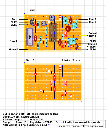
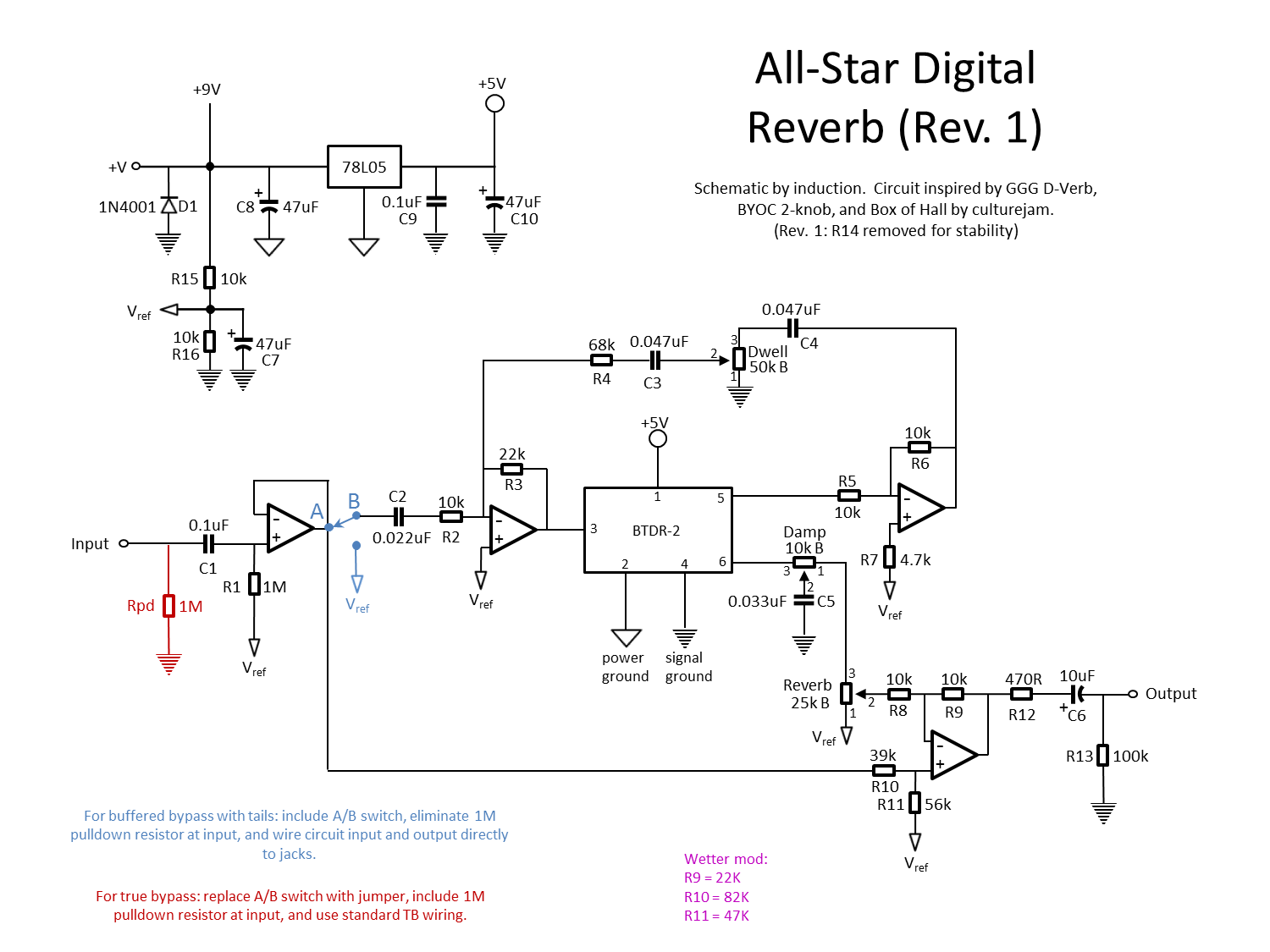
The damp knob in the box of hall circuit is not identical to any of these cases, but it is similar to both the tone control in example 3 and the voltage divider in example 1. The resistance between lugs 2 and 3 and the cap to ground from lug 2 provide the R and C values in a variable low pass filter with corner frequency fc = 1/(2*pi*R*C) (simply put, all frequencies above fc are attenuated to ground in proportion to their frequency). Unlike the tone control, the damp control is in the signal path, not in a sidechain, and the 10k pot value provides a constant resistance for the signal which travels from lug 3 to lug 1. Note that the resistor (R7) coming from BLT6 (the second brick output) is also 10k. These resistances minimize the interaction of the two output signal by forming a simple resistive mixer.

To replace this control with a resistor, treat it as the voltage divider in example 1: replace it with two resistors that match your favorite setting, and attach the cap to ground to the junction between them. Since you get no response from this control at all, you can just use a single 10k resistor and put the cap on either side. It's possible you can just leave the cap off, which may or may not make the reverb signal brighter. If there is a difference with or without the cap, pick whichever you like better.

In this particular case, I'd say you can also just remove the pot entirely, which removes one of the brick outputs from the circuit. My breadboard experimentation indicated that the sound from a single brick output is the same as the sound from both outputs mixed together, but YMMV, so it's up to you.
Reply | Threaded
Open this post in threaded view
|

Re: Omitting Potentiometers...(replacing w/ trims/resistors)

Freppo
Just wanted to chime in and say that my Box of Hall builds have the same problem, the damp knob does nothing. I built the heavenwithinmodded version and used a medium reverb in one build and a long reverb in the other. :/

Anyway, I really recommend the ghostecho reverb layout by Harald Sabro for use with your Belton reverb tanks. Sounds really great! His layout have a couple of problems, but another builder has posted a corrected layout that works 100% in the comments section on the ghort echo page.

/ Fredrik
check out my building blog at www.parasitstudio.se
Reply | Threaded
Open this post in threaded view
|

Re: Omitting Potentiometers...(replacing w/ trims/resistors)

alltrax74
In reply to this post by induction
Thank you very much Induction, your posts are always very instructive
Reply | Threaded
Open this post in threaded view
|

Re: Omitting Potentiometers...(replacing w/ trims/resistors)

alltrax74
In reply to this post by Freppo
There seem to be a mistery around this damp pot...

I'll try the Ghost Echo, I like the attack control
Reply | Threaded
Open this post in threaded view
|

Re: Omitting Potentiometers...(replacing w/ trims/resistors)

induction
After breadboarding a bunch of reverb circuits, I combined all the features and voicings I liked the best into my own circuit. I included the damp pot from the box of hall but gave it more available treble rolloff. It also has a dwell knob. It's capable of many different sounds. I like just a touch of reverb with the damp knob turned down (darker), to add some space around the sound, but with the dwell and damp knobs dimed, it has a shimmery, sustaining, ethereal sound that is very different from the spring reverb emulation you usually get with these bricks.


Here's a modded version for someone who requested double the amount of available wet signal:


Here's a crappy demo. If you watch the parts where I twiddle the knob on the right (especially around 4:06), you can hear the effect of the damp knob. It only affects the tone of the wet signal, the dry signal is left alone.

Here's more details about the circuit and some gut shots.
Reply | Threaded
Open this post in threaded view
|

Re: Omitting Potentiometers...(replacing w/ trims/resistors)

Freppo
Wow! That's great work!
I liked the demo. No need to excuse your playing.
Something about making demos... My playing always suck as soon as I hit record :P

Might actually give your reverb a try, since I have a reverb-brick left. :)
Nice idea to mount the brick on the solder side of the board!

cheers
/ Fredrik
check out my building blog at www.parasitstudio.se
Reply | Threaded
Open this post in threaded view
|

Re: Omitting Potentiometers...(replacing w/ trims/resistors)

Freppo
We should have a subforum where people can post their own schematics/layouts and mods.
Seems to be more and more stuff coming up. :)
check out my building blog at www.parasitstudio.se
Reply | Threaded
Open this post in threaded view
|

Re: Omitting Potentiometers...(replacing w/ trims/resistors)

Freppo
I built the All-star reverb, no luck though. I only get clean signal.

Triple checked and cut the gaps and everything seems ok..
Maybe my reverb-brick is broken. :/

Btw, I noticed one cut too many on the first row.

Back to the troubleshooting...
/ Fredrik
check out my building blog at www.parasitstudio.se
Reply | Threaded
Open this post in threaded view
|

Re: Omitting Potentiometers...(replacing w/ trims/resistors)

induction
This post was updated on .
Thanks for building it, I'm honored.

You're right. There used to be a power filtering resistor on the top row that I removed from the component side layout, but I forgot to remove it from the track side layout. Thanks for pointing it out. The veros have been corrected.

Other than that, this layout has been verified on FSB, so it should work fine. Are you doing the true(ish) bypass version or the tails version? When you say you only get clean signal, does that mean you get clean signal when the effect is on, or only in bypass?

If you want to post pictures of your build, I'll take a look.
Reply | Threaded
Open this post in threaded view
|

Re: Omitting Potentiometers...(replacing w/ trims/resistors)

Freppo
I'm doing the true bypass version.

When the effect is on all I get is clean signal.
The reverb knob drops the volume alittle when turning CW.

I built another reverb today (the original Box of Hall) and got the same problem.
Gonna put this on hold until I can try with another reverb-brick.

Cheers
/ Fredrik
check out my building blog at www.parasitstudio.se
Reply | Threaded
Open this post in threaded view
|

Re: Omitting Potentiometers...(replacing w/ trims/resistors)

Freppo
I got a few new reverb-bricks from banzai today.
5 minutes later...Now the All-star reverb works and sounds amazing.
Great work!!!

I highly recommend it for anyone wanting a good reverb!

cheers
/ Fredrik
check out my building blog at www.parasitstudio.se
12