Hey guys,
I've been a lurker here for a while and I love how vibrant and helpful the community is and I've learnt a lot from it over the past number of years. I want to share with you an idea for a veroboard-inspired PCB system that I've been developing for quite a while. I'd also like to give out free PCBs and kits over the next while, to those who have contributed to the community. I've included background on myself and the company I started to give you a bit of context to where this project grew from.
Myself and the company’s backgroundMy name is Thom and I run a small company in Ireland called
http://www.maker.ie. For the past 4 years I've been introducing people to pedal building and all areas of audio electronics through hands-on workshops.
My background is originally in science which really couldn't inspire me so I followed up with a masters in Music Technologies. It was during my masters that I really got into audio electronics, starting off with circuitbending and moving quickly on to pedal building. I started running workshops with my classmates and I found I really enjoyed teaching them and they really seemed to like making stuff. Anyway, before I'd finished my masters I was running workshops in Dublin mostly to friends and friends of friends, and the response was really positive (I'd a little previous experience teaching in music and science). After I finished the course, myself and another classmate had the thought that if this many musicians in Dublin were as interested and excited about DIY audio electronics as we were, there might be a sustainable market for a business. So guided by impulsive and youthful naivety we enrolled in an entrepreneurship development programme at our college and began sculpting a business plan and conducting market research.
At the end of the programme we were lucky enough to win their business development award and secure a free office on campus for a year. Our market research came back very positive, and our workshops were still popular, so we decided to give starting a business a go, initially on a part-time basis, to see if there was any traction.
About a year later, after a dozen or so workshops, I was lucky enough to get onto an accelerator programme that provided enough finances to allow me to work on the project full time. It has been about 18 months since. We now have three staff and have just relaunched our site (and have developed a few new products and kits) but what I want to present to you guys is the manifestation of 4 years of working with musicians and trying to solve what I see are some of the frustrations of DIY guitar pedal building, while maintaining the better aspects of the use of veroboard. It also ties in with my very firmly held belief that anyone and everyone is capable of DIY electronics, provided the platform for learning is right.
The IdeaSo this is it; the B.I.Y. (Boutique It Yourself) PCB Layout [url]
http://imgur.com/c1sIvdG.jpg[/url]
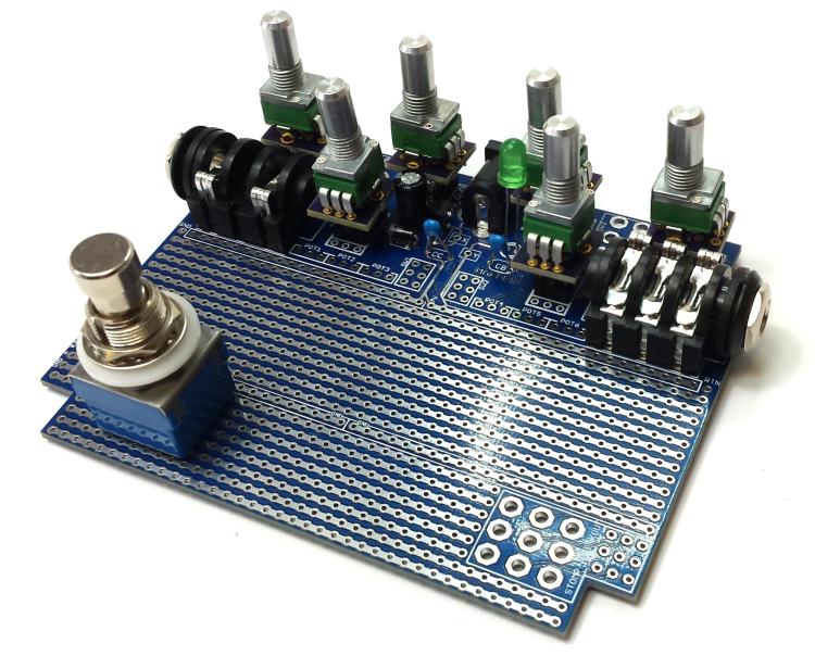
BIY Prototype build: [url]
http://i.imgur.com/7JqiTZ8.jpg[/url]
I'm keen to try and make it easier for musicians to get into DIY. I believe by de-jargoning literature, increasing the approachability of the technical process and bringing down the overall cost of DIY there is nothing stopping anyone getting involved and reaping the creative rewards it has to offer. Logically, this means empowering every musician to create their own, unique "boutique" equipment.
The B.I.Y. PCB (and kits) are my attempt to meet these objectives for guitar/bass players and pedal builders. When I started the design process for this project I had the following objectives:
- Increase long-term build reliability
- Minimise opportunities for build error
- Reduce build time
- Maximise flexibility/mod-ability
- Minimise Cost
- Stimulate community-led design innovation
Let's look at how I tackled each of these objectives...
INCREASING LONG-TERM BUILD RELIABILITYThis is possibly the most important objective. We all want our projects to be as close to "gig-safe" as possible. As exciting as it is to build something and hear it working; if it stops working after a week/month/year (especially on stage!), you are just going to get pissed off and perhaps abandon DIY electronics altogether.
To try and solve this issue I went with a single PCB that fits neatly into a 1590B (Hammond - in the USA)/27134PSLA (Eddystone - EU/UK) that requires no off-board wiring. All components (shrouded inputs, stomp, pots, etc...) are soldered directly to the board. There is virtually nothing to come loose from tossing it in your gig bag and it removes any pressure on the wiring from the pots, inputs or stompswitch from over use. The only wiring required is board-to-board (for jumper wires and connecting to potentiometer inputs).
MINIMISE OPPORTUNITIES FOR BUILD ERRORThe design has been heavily inspired by the vibrant vero/stipboard community and the flexibility the medium offers. However there is one huge headache with stripboard; having to cut on the reverse of the board and place components on the front. I can't tell you the amount of times I've made a trace cut in the wrong place only to realise later in the build, or worse, frying an IC because of some messy off board wiring mistake or jangly piece of stripboard shorting against the enclosure. Trying to read from a printout or screen can also easily lead to a mistake that can in turn lead to hours of head scratching followed by frustrating desoldering. This is where I think this project makes a huge leap over stripboard while maintaining all its benefits:
- On B.I.Y. PCBs, all trace-cuts are made on the front of the board; the same side you are placing the components!
- All wiring to pots, switches and jacks is taken care of by the board; no more jungle of wires crammed into a tiny stomp pedal!
- Maker.ie will provide component ''maps'' for each project, made to scale that can be printed and stuck/taped to the front of the board
- Maker.ie are developing an augmented reality app that will show you exactly how each project should look in 3D when completed and at each stage of the build (resistors, capacitors, ICs, wiring, etc...)
Augmented Reality App Prototype Stills [url]
http://imgur.com/a/I3pdS[/url]
MINIMISE BUILD TIMEThe biggest savings in build time will most likely come from:
- Reduced troubleshooting
- No off-board wiring
- Component maps remove the need for referencing screen or printout.
STIMULATE COMMUNITY-LED DESIGN INNOVATIONI want this build platform to help stimulate innovation and experimentation within the guitar pedal design/modification community. This proejct is released under an open hardware licence (our learning material is also all Creative Commons) and we will be making the photoshop files for creating your own scaled component maps freely available. I'm also keen want to reward the huge amount of often urecognised innovation within the guitar pedal community and am proposing the introduction of quarterly design competitions. As well as winning prizes in these competitions, other ideas include offering winning original designs a 15% Licence Fee for the sale of kits of their design. 15% of sales of kits from other established designs would go to a worthy charity. I'm are still toying with this idea and would love the community's feedback on it.
MAXIMISE FLEXIBILITY/MOD-ABILITYThe free build area of the board is designed like strip/veroboard with tracks of connected holes through which to insert components for soldering. This provides the same level of flexibility and customisation that strip/veroboard offers and leaves the user free to draw from the huge wealth of designs and modifications created by the amazing stripboard community.
I've introduced a number of innovations onto the B.I.Y. PCB that offer the builder a high level of flexibility and convenience:
- A dedicated area on the board for creating 1/2Vcc (or another reference voltage) for biasing opamps and transistors.
- Dedicated ground and power rails. These are split in the middle and fed from two different points. Trace cuts can be made to free up the rest of the track. On the ground plane this minimises the return path of the signal and on the power rail it, well, you'll see in a second....
- Space for a Voltage Regulator which is selectable by making specific tracecuts. This provides for 3 options:
1. Do nothing - DC power comes in and goes to the power rail.
2. Make a trace cut and now regulated (cleaner) positive voltage goes to your power trace
3. Make a 2nd trace cut and now you have regulated power to half your power rail, and DC input to the other half. This is great if you are using a digital chip (3.3V or 5V) alongside opamps for example.
Board Innovation images: [url]
http://imgur.com/a/rMzF5[/url]
MINIMISE COSTBy using the same board our company can purchase the PCBs in bulk dramatically reducing costs. This same principle also applies to the components (electrical and mechanical) which we will have available through kits should you wish to shop with us.
DESIGN CHALLENGESOne design challenge I have struggled to solve is soldering the pots directly to the board. I feel this is important in order to keep build reliability high to match the height of shrouded jacks, and the stomp switch. Soldering to the board directly means the spindle of most common 9mm potentiometers does not reach high enough above the surface of the enclosure to attach a control knob. There are apparently long spindle 9mm pots out there, but we have had trouble sourcing them and they are inevitably going to be reasonably expensive (and remember we are trying to minimise cost), and we want these boards to be as accessible as possible.
One solution I've have come-up with is to use male/female pcb connectors to raise the physical level of the pot above the board, while still keeping all soldering to the PCB. This means a little extra soldering which maybe isn't ideal, although there is no off board wiring. If anyone out there thinks they have a solution to this that doesn't significantly increase cost or build time we would love to hear from you!
NEXT STEPSI will continue to strive to improve our design as we get feedback from the community and we are already working on a larger version for a larger enclosure design. We will also be designing a 2 stomp version for effect switching.
Larger Board Early Prototype Image [url]
http://imgur.com/wqw95RX[/url]
We are also keen to finish our augmented reality app. If there is anyone out there with experience in Unity we would be interested in hearing from you.
This project has been born out of a love for pedal building and the amazing community around it, and a desire to see more people get involved in this very rewarding and creatively freeing pursuit. If you have any suggestions of ideas or feel you can contribute to the project, please get in touch with us at
info@maker.ieThanks (and very sorry for the megapost)!
TL:DR - Guitar Pedal building PCB that: Increases reliability/reduces build time/reduces opportunity for errors/stimulates community-led innovation/maximises design flexibility/minimises cost - would love feedback - some free stuff


 Side mounts are so incredibly pedal board inefficient.