Orange distortion

classic Classic list List threaded Threaded
3 messages Options
Reply | Threaded
Open this post in threaded view
|

Orange distortion

kavelj22
hi Guys...

i'am new here, i just made my first board. it still need to be figured out the green pads, that's why you have the link to the originalk schematics. Insted of original IC i used the OP2604, just to give it a try. It is still posssible to use the orignal IC if you can get it somewhere.
I will appreciate comments, like what could be done better and if someone finds any errors!!!

The board is quite big 34x20, but it is possible to split it on half and make it like double layer or something. You will see.

So here's the boards:


And the link to the original schematics:

http://byocelectronics.com/orangedistinstructions.pdf

Thanx,bye.

Reply | Threaded
Open this post in threaded view
|

Re: Orange distortion

IvIark
Administrator
Thanks for sharing
Reply | Threaded
Open this post in threaded view
|

Re: Orange distortion

Freppo
This post was updated on .
In reply to this post by kavelj22
You would be alot better off leaving some things from the layout, like bypass switch connections and jack-ground connections. LED resistor and connection and so on. Those things are better wired off board.  It will save alot of space on the layout. As long as you have a single connection for each connection like +9, ground, input, output ect. you'll be ok. A good layout keeps all the pot connections at the left and right sides IMHO, and prefrebly the same side for the same pot.

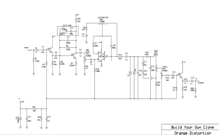
The transistors (Q1-3) needs to me marked out on the layout though.

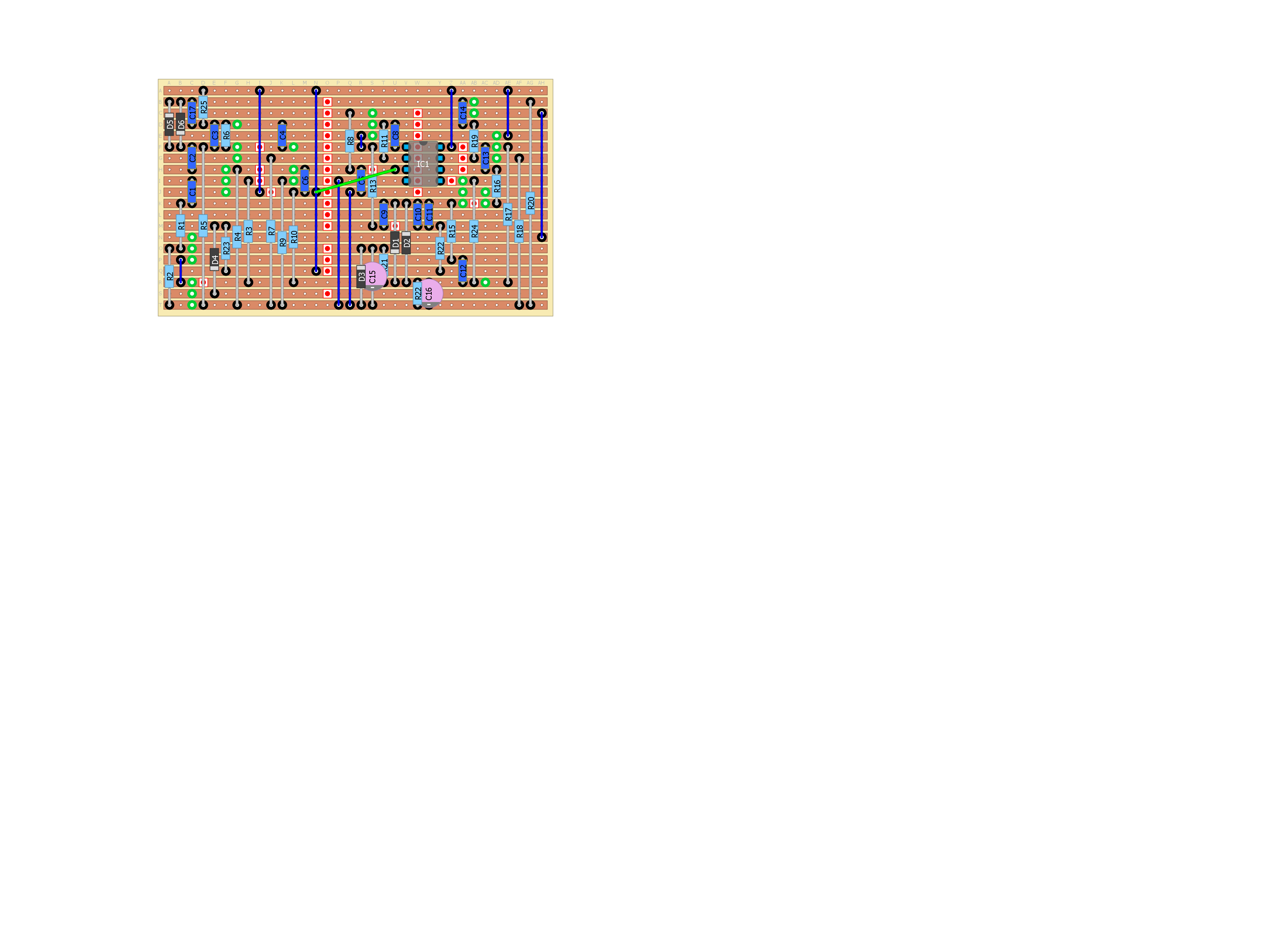
This is how I would see this schematic for vero:


Overall, not a bad start. Keep going. :)
Have a look a few other schematics and start with something simple.

cheers / Fredrik
check out my building blog at www.parasitstudio.se