Hello Solderholic, I hope all is well.
You want the signal from the input jack to go directly to the buffer first, then out of the buffer to the input of the circuit. The output of the buffer also goes to the switch. The switch swaps between the buffered output and the volume pot. There are some problems with the way you have the signal flowing in your layout - you have added another buffer, which is not needed. The layout already has a buffer, so you do not have to include another. The signal also loops in a way that does not work.
You can see how it works here on the G2
http://3.bp.blogspot.com/-DSD3O8O8mx8/U5rGpCi5KgI/AAAAAAAAHzQ/u5fPoB7Dgwo/s1600/Cornish+G2+bypass+buffer+wiring.png
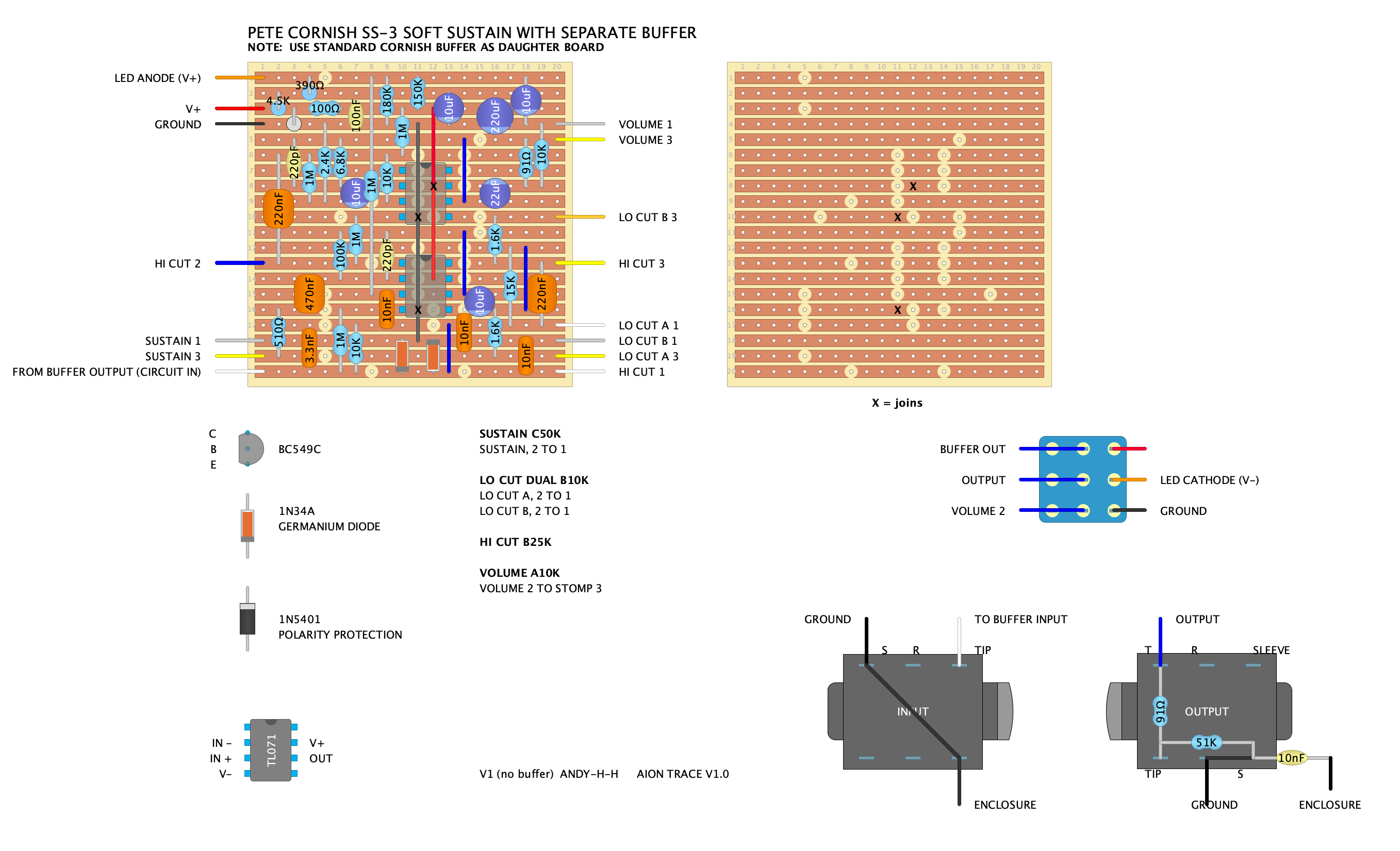
I've made a smaller layout for you without the buffer if you would prefer to keep them seperate. I have not tested this, but it looks right.
I have added the Jack Orman LED mod too, just because I like it. Easy to remove if you don't. Link here
http://www.muzique.com/lab/led.htm
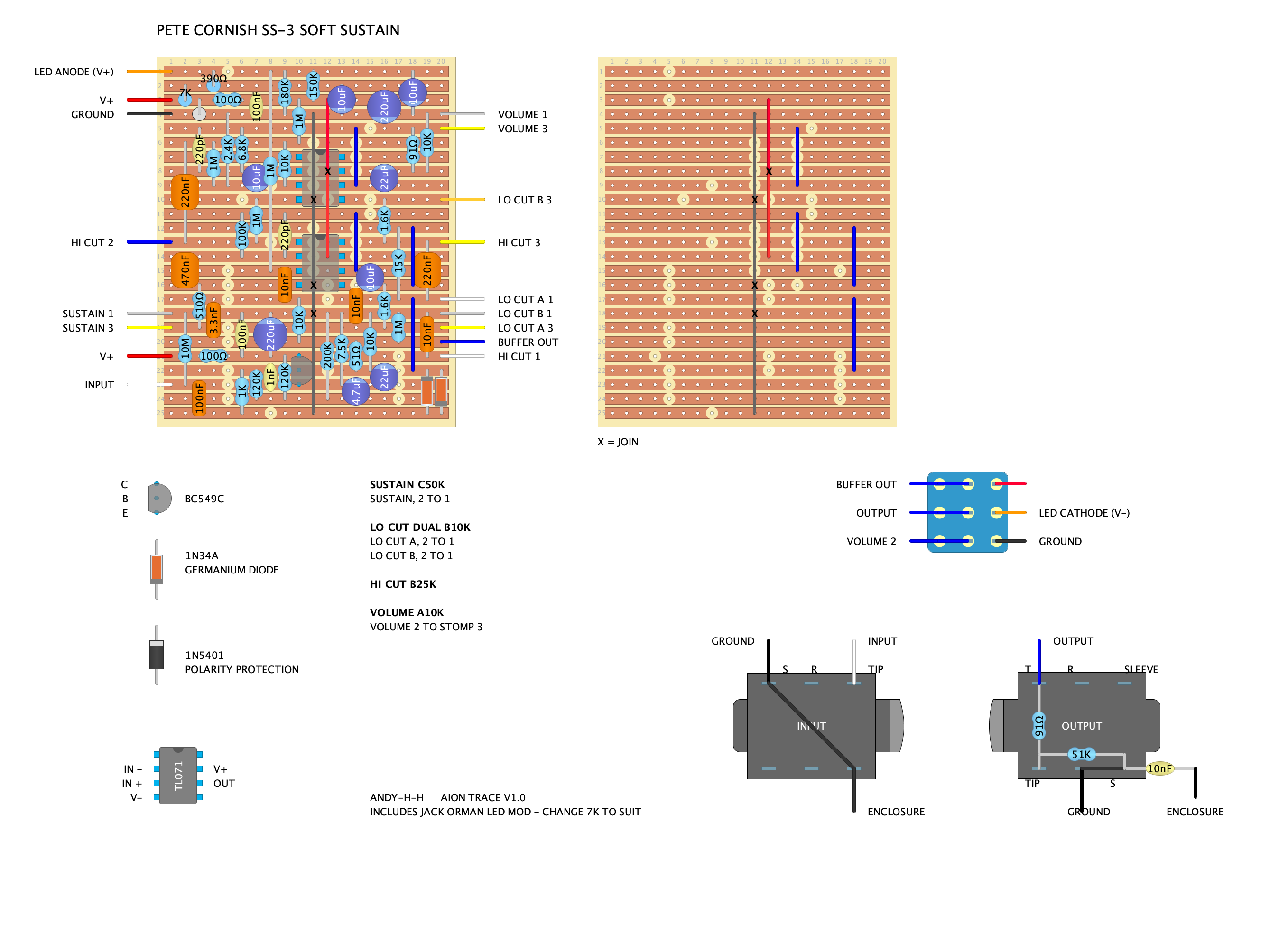
Here's a version with the buffer included (no daughter board required)
