Ross Phaser query

12
12

|
Greetings folks,
I am rather new to this, and have gleaned a lot of very helpful information from this site, but I wonder if I could ask about my latest pedal build? A little background - so far I have built a Lovepedal Woodrow, a WH Red LLama, a Rockett WTF and a Madbean Cave Dweller. A few niggles aside (and some very messy wiring), they have all worked first time and Ive been happy with them. I have a little knowledge of electronics - I know what most of the components are but not necessarily how they interact. Right, to the question. I finished up last night a Ross Phaser (with intensity mod) from this site, but I think there might be something amiss. I get sound on bypass, and there is a phasing sound when engaged (either the guitar sound or background ?LFO sound). The rate control seems to work backwards (I tried rewiring the pot, with no difference), and has a *very* limited range of use (maybe first 1/4 turn). Neither the intensity nor the regen pots appear to do more than very subtle adjustments, and I can hear no discernible difference whichever way the vibrato/phase switch is switched. As yet I haven't measured any voltages (mostly because there are 56 pins on the board), and the pedal *is* working, so I cant imagine there are any major issues. I was careful to check for solder bridges and triple checked all cuts/links. I also wondered if it may just be the way the pedal is supposed to sound? If anyone could offer any suggestions, I would be very grateful. And again, thank you for this rather fantastic resource you have put together. Adam |
|
|
Its hard to say without seeing what you've built.
Post some pictures of the top and bottom of the board, there are some eagle eyed people on here. Pin voltages are really helpful so if you can measure them and post the results that will give us a steer. How close dies it sound to the demo http://tagboardeffects.blogspot.co.uk/2016/05/ross-phaser.html Also have a look at the comments on the build page, there are usually some people who have gone through debugging a build so you might find a similar error. |
|
|
Hi,
Thanks for the reply - I figured that the pin voltages would be requested, I shall try and get that done tonight. I shall also post up some photo's - but I warn you it isn't straightforward to see through my soldering! It sounds a *little* like the video on the layout page, but that is of the original Ross Phaser and not the clone. I had also looked through the build comments (where I have learned a fair bit so far on other schematics), but there aren't too many of them. And none that really address the issue I have had. There is a brief mention of the rate pot possibly being reversed, but no discussion beyond that. As the original layout was released last year, I felt that the 'debuggging' section of the forum would be best to reach the collective knowledge :) Cheers, Adam |
|
|
Dude, you are totally right to post in debugging. I was suggesting that sometimes you can find people that have had similar issues by looking through the comments, and that sometimes you can get a clue to what is wrong. I've always found modulating things really hard to debug. A meter, an audio probe and a schematic are essential when things don't work. I normally test that I am getting voltage where it is supposed to go i.e IC pins (check the interweb for the IC type and find a pinout diagram), transistors etc. Make sure that if your IC has a reference or bias voltage that is going to the correct pin(s) and that it is the correct voltage (it's common for the ref voltage to be half of the source voltage) Check that any transistors are biased correctly. Follow the audio path through the vero using the schematic and an audio probe, this can be hard to do but you'll get the hang of it. And if you do post in the debugging section make sure that you provide as much info as possible, pictures, voltages audio descriptions etc..... you are much more likely to get a response. Hope that helps, get some pictures and voltages up and we'll see what else we can do. |
|
Administrator
|
In reply to this post by Kalimna
The backwards pot is simple. You need to switch the wires to lugs 1 and 3 on the rate pot.
The layout says connect lugs 2 and 3 of the rate pot together. That is either a mistake in the layout or you linked lugs 1 and 2 instead You will need to undo that link or get a new pot to make that pot work properly. Once you have no link there, the wires will go to the two lugs that used to be linked together |
|
|
Again, thank you for your help. I shall have a look again tonight. And also google the schematic.
Travis - may I just confirm what you are suggesting? The layout indicates a wire to go to both lugs 2 and 3, and also a separate wire to go to lug 1. If I have followed your instructions correctly, I will have one wire going to lug 3 and another going to lug 2, with nothing to lug 1? The layout also suggests wiring lugs 1 and 2 of the intensity pot together, then to the middle pole (2) of the vibrato/phase SPST switch - if I removed the link here might that improve the function of the vib/phase switch? Cheers, Adam |
|
Administrator
|
Yes that is correct (one of the lugs will be unused).
Here's the deal.. when you see two pot lugs linked together on a single gang pot like that, the pot is being used as a variable resistor. A variable resistor only needs to use two of the lugs which are the wiper (lug 2) and either of the outer lugs (1 or 3) Lug 2 is always used, whether the other wire connects to lug 1 or 3 will determine the direction that the pot "works". In other words, when the pot is working backwards you swap the wire from lug 3 to 1 or vice versa. Now why link the wiper to the unused outer lug when you only need two lugs for a variable resistor?? Our fearless leader Mark likes to do this for redundancy. If for some reason the wiper of the pot fails, the pot will act like a resistor that is always at the max resistance of the pot. This is obviously preferable to having the pot act like an open circuit which is what happens if the wiper fails and you only used two lugs. Why not link the two lugs together? Well fundamentally it is unnecessary, but it also makes the pot harder to work with if something changes and you need to use the pot in a different configuration. Anyway I hope that wasn't confusing and I hope that helps you understand. You can decide for yourself if you want to link the lugs together on variable resistors. Personally I don't, lots of people do. It's all personal preference. Ask any questions if I confused you about anything |
|
|
In reply to this post by Kalimna
Ok, I have gone over it with a DMM (black to ground, red to pins, supply from Fuel Tank @ 8.95V) with all the pots at minimum, then all the pots at max. I checked a few on LM13700 no.3 with the vib/phase switch in both positions but there didnt seem to be any difference. Looking at the forum schematic, I have numbered the IC's
top left LM13700 - 1 bottom left LM13700 - 2 top right LM13700 - 3 TL072 - 4 and used standard pin numbering (start lop left at number 1, working anticlockwise) 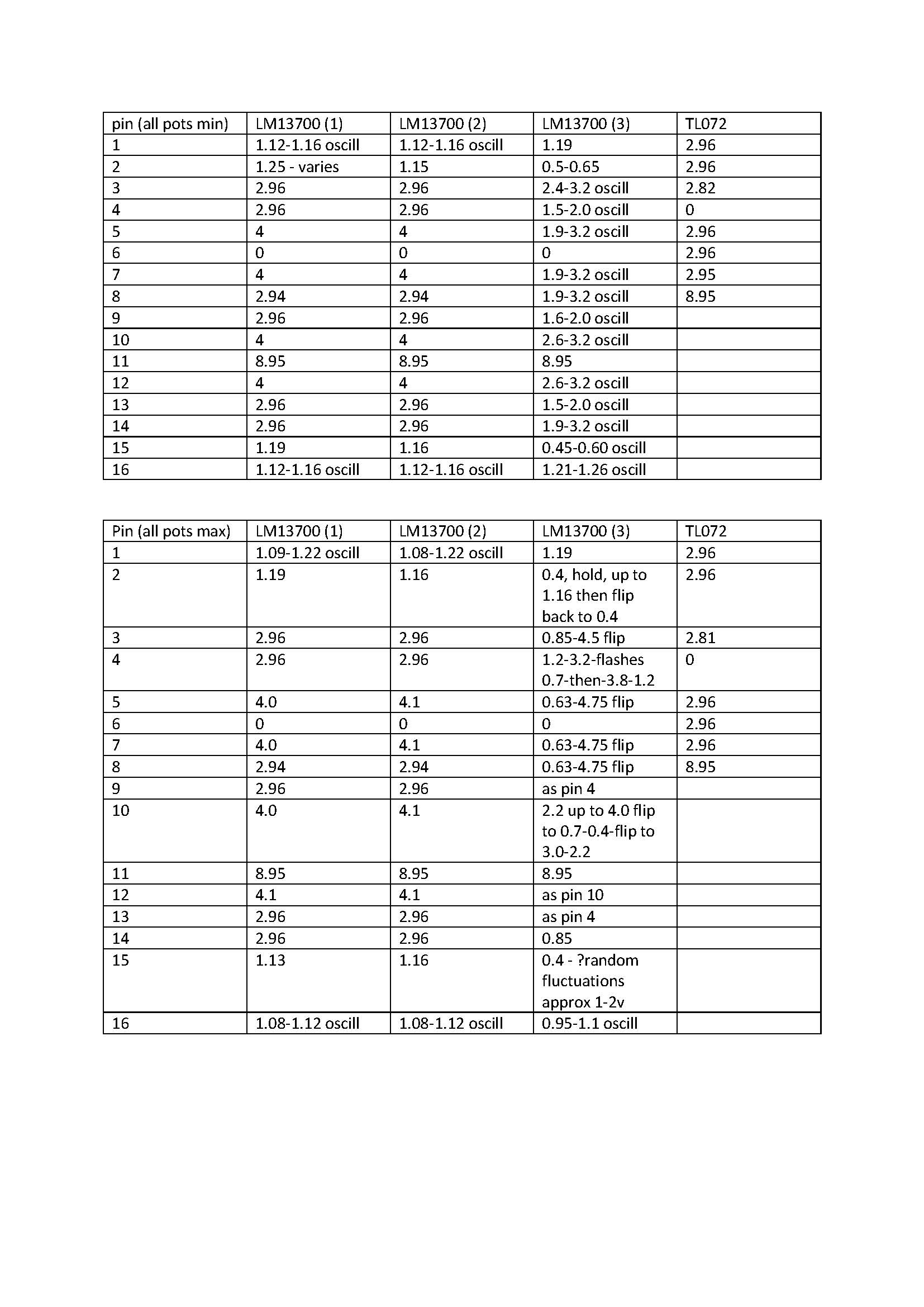 Here are a couple of photo's of the pedal. I think I have included all the relevant parts. There is no battery clip.  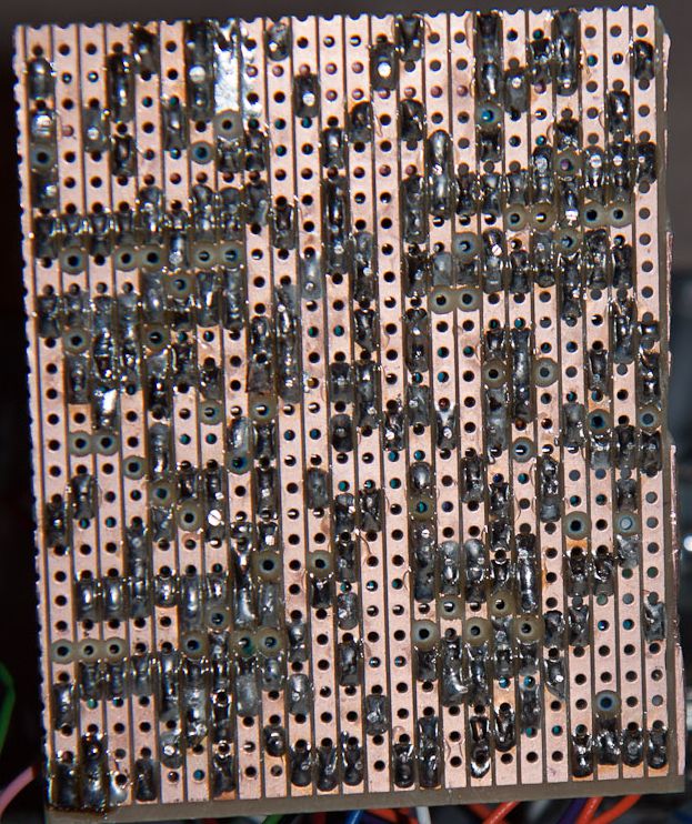 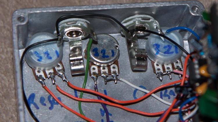 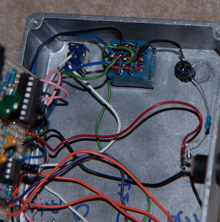 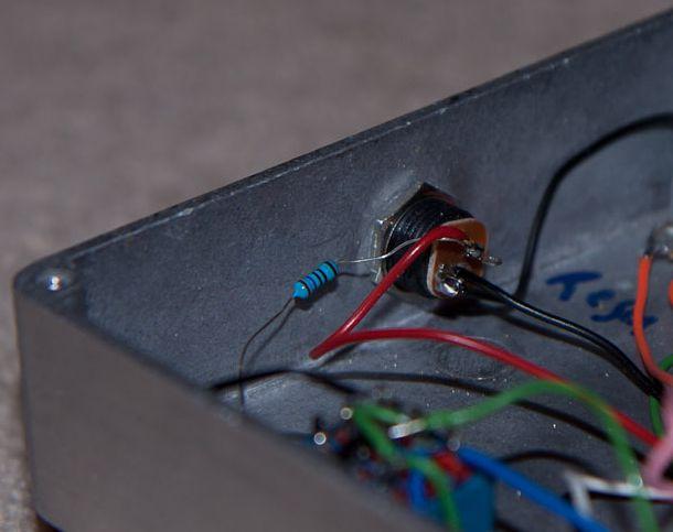 If I can post anything else that might be useful, please let me know. Thanks, Adam |
|
|
Travis - thanks for your very clear explanation, I must have been editing my photo post when it came up though! Ok, so I understand the use of a pot as a simple variable resistor, and also the reason for linking two of the lugs.
Again, if I understand correctly, the linkage is there as a 'safety' feature, but fundamentally shouldnt affect the sound of the effect. Looking at the pin voltages, I guess IC 3 is where the phasing is happening, with the oscillations and flipping. Ground and supply voltage seem to be appropriate, and would I be correct in thinking that the TL072 values would be different when a guitar signal is applied? Cheers, Adam |
|
Administrator
|
You are so organized and great... a debuggers dream! It's a lot for me to digest right now but I'm taking a look at this. It seems that this is based on the Tonepad schematic
In the Tonepad schematic the LFO is coming from IC4. In the layout, that's gonna be the 13700 at the upper right side. Then in the schematic you will see that IC2 and IC3, the other two 13700's are where the actual phase shifting stages occur. Gotta take a closer look at your info, and hopefully others will join too cause I'm definitely not the best remote debugger around. |
|
|
In reply to this post by Kalimna
Hi Adam
Looks like a nice tidy build. The most obvious issue would be your vref voltages. They should be around half your supply voltage...so around 4.5v. Yours seems to be 2.92V. So either 1 of your 10K's isn't 10K or there's someone greatly loading down your bias voltage. Try this... Take out all the ICs and measure the voltage on the row between the Ground row and Sw1 row. It should be half your supply. If it isn't then start looking hard at your resistor values and placement/shorts etc. If it is good then..... Replace each IC one at a time, measuring that same row after you install each one. If the vref measurement drops after you install one...you might have found a dodgy IC. Also...is that 100p definitely 100p? Thats the only thing I could spot from your pics that raised a question. As i said....your build looks great. Let us know how you get on. |
|
|
In reply to this post by Kalimna
Travis, Ciaran,
Many thanks for your time, effort and kind comments regarding my build. I'll be honest and say that Im having a bit of a time of it making the wiring as neat as many who post here do - my excuse is that Im using single core..... Anyway... I have had a quick look at the voltage on the row as you suggest (row between Ground and Sw1). It is a smidge under 2V. So I guess that means one (or more) of the resistors are incorrect, or there is a short somewhere. Now, I have tried to look at the schematic in a little more detail, and I notice that from the row in question there are 2x10k resistors to ground and 9V (via some circuitous links)- would this be a voltage divider for Vref? Or is it more complicated than that? If so, then I assume that would be a good place to start looking for errors. Are there any other areas I should be concentrating on, or is it 'check one component at a time until something flags'? Am I also correct in assuming that I cant just measure the resistors-in-circuit as they will form parts of a network and give an erroneous value on the DMM? Regarding the 100pF cap, I haven't measured it, but the number on the body suggests it is correct. I will check them all again, however. Due to 3x12hr shifts starting friday morning, I may not get much more done over the weekend, but I am grateful for your help and will report back when I have checked things over again. Cheers, Adam |
|
|
Yip, you read the layout right. It helps to always reference the schematic to the layout and your build when debugging so I've included it here
You may have to visit this link first. So yeah, the 2 10K's make a voltage divider and this is used as a reference point for IC inputs to avoid clipping your guitar signal. You can see these 2 resistors in the bottom left of the schematic (the cap provides some filtering) and the bottom right and bottom far left of the top left 13600. Did you measure that row with the IC's in or out? If out then yeah you have a problem somewhere with this network. It could be a wrong valued resistor, a short, another component connected to vref that shouldn't etc. Basically it could be anything but at least you've narrowed the search area. Also yes, measuring a component in circuit with a DMM can't be relied upon for exactly the reason you gave. Try reading the colour bands and compare them to a chart online (there's a host of phone apps that do this very quickly now). Then of course use your DMM set to continuity and check that only components that are supposed to connect to each other are connected. Any that are not supposed to...fix. Here's the layout overlaid with the power lines to get you started. I tend to do this before I start really big builds...fully prepared for it to go horribly wrong lol! Red = 9V Green = 4.5V Black - GND (0V) 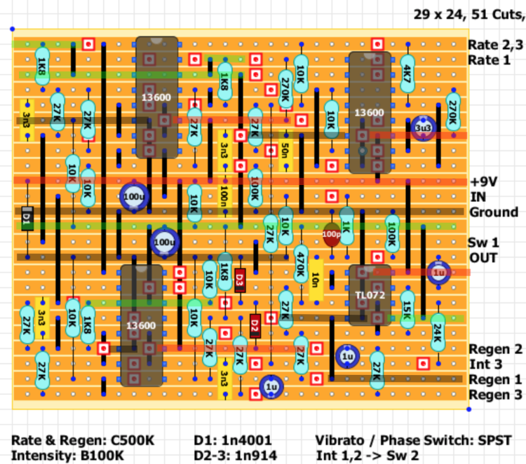 ...and now that I've done that I think I've spotted an error on the layout. There seems to be an extra 10K that I can't account for on the Tonepad schematic. Pin 3/14 on bottom left IC...vref to gnd. This looks like it would mess up our vref divider as it's in parallel with the other 10K in that network. Might be worth lifting one of it's legs and seeing what changes? Hopefully Alex will chime in as I may have missed something. |
|
|
...although I must stress Adam that this layout has been built and confirmed as working so there is still something else going on with your build. So I'd do all the usual checks...values, placement, continuity etc.
Good hi res pics in good lighting will really help us. Post them to imgur or photo bucket and link them here. That way the forum won't compress them and mess with the quality. |
|
|
Ciaran,
Very briefly, here is a link to higher res images of the above photo's. If they aren't good enough, I shall try to take some more in better lighting, but it wont be till monday at the earliest. http://imgur.com/a/4VjI4 I shall digest your two posts above, and note your comment regarding the layout being verified already - I have no doubt that the error is in my build somewhere. It rather amuses me on some of the layout comments when people have difficulty getting them to work and seem to assume that there is a layout problem, and not their own build despite several people advising them otherwise.... Whilst I know of the colour codes for resistors, I have had great difficulty actually seeing the different colour bands on those I have bought (my eyes just aint what they used to be), so it might end up being easier to de-solder and measure.... Either way, your help is truly appreciated. Thanks, Adam |
|
|
Hello,
I havent yet had the chance to get the soldering iron out again (the weekend has been wake-up, work,home, dinner, sleep, repeat), but have gone over the board again. As far as I can tell, the track cuts/links/capacitors are all correct. The resistors are in, I think, correct places but I am not certain the values are correct. Before I start de-soldering, I wonder if anyone could confirm the value of the resistors in the attached two photos? I realise that I should be able to work this out myself, but I would like another pair of eyes, particularly as I think what was written on the strip of resistors may not match the colour code. Anyway, here are the photos : 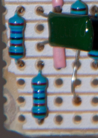 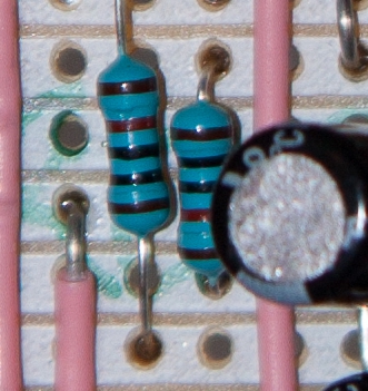 I havent included what I *think* they are, nor what they *should* be deliberately. Again, many thanks, Adam |
|
|
They look correct to the layout (27K and 10K). Reading them the other way would give you 200M (not available in that package) and 120r (they would burn up in the divider)
Here's some advice on being methodical when troubleshooting I hope will help Be methodical in your testing and always troubleshoot with a schematic in front of you. 1. Visual examination Compare the layout with your build, looking for misplaced components, wrong values, missing cuts/links etc 2. Continuity test Set a multimeter to Continuity mode (or resistor mode if it doesn't do continuity) and probe each connection by following the schematic. Place the probes on the component legs, not the solder. This will help find any cold joints. This also includes any wiring 3. Variable components test Test all your pots with a meter. Set to resistance mode, place 1 probe on lug 1 and the other on lug 2. No sweep the pot while checking the meter shows a rising resistance the full way up. The the end of the sweep the meter should show the pots full value (within 20%). Best to do this when the pot isn't connected to the circuit. 4. Voltage test Measure DC at all the important places. The IC, power, vref rail etc. 5. Audio Probe Last resort before throwing the thing out and excepting failure. Follow the schematic and probe for your guitar signal. If its on one side of a component in the signal path but not on the other you either have a bad component for some short nearby. But if you've completed the last 4 steps then the probability is high you've a bad component. If you're happy you've completed checks 1 to 4 and found nothing...then it's probably time for 5, the Audio Probe. This will allow you to follow your guitar signal through the circuit and hopefully find a bad component. http://diy-fever.com/misc/audio-probe/ Take a jack cable and cut off one end. Solder a 100n to 1uF non polar capacitor (voltage rating is irrelevant...so long as its rated higher than 9 volts) in series with the tip wire. Attach the ground wire to the ground of the circuit your testing. Now its a simple matter of plugging in the other end of the jack to your amp, plugging a guitar to the input of the circuit and, using the probe, poke at all the components where your signal should be. You'll need to follow the actual schematic, not the layout to do this. We'll get there eventually lol. Good luck |
|
|
Ciaran - thanks again for your patience in helping out a novice. I think my eyes need testing as I read the colour codes as Black-Brown-Black-Blue in the first photo, and Brown-Black-Black-Brown in the second.
However, step 1 I was happy with. Step 2 - I shall re-check the continuity Step 3 - Fair enough, but would that answer why the vRef was off? Step 4 - Will do - with the schematic I suspect if nothing shows up simply, then I will re-do the board and one-by-one remove components, check, and replace in new board. I understand the necessity for being able to de-bug, but I wonder if a smaller circuit would lead to less frustration. Perhaps checking as I go along rather than 'put everything in' then check when it doesn't work. Either way, this is a valuable laerning experience. Cheers, Adam |
|
|
Ciaran - I have lifted the 10k as suggested, and the voltage going to pins 3/14 is now a little over 2.5v. This is without the ICs in place.
Cheers, Adam |
|
|
Then you've proved that there's still a short/misplaced/wrong value resistor pulling this bias voltage down. The only place a load can come from is the IC's....and they are not in. Set DMM to continuity and follow the steps above. Getting there

|
«
Return to Debugging
|
1 view|%1 views
| Free forum by Nabble | Edit this page |