Rotary switches, whut?


|
Hey Guys + Girls,
It's been a while! Hope everyone is still doing ok over here. Darker days ahead and they are seem perfect for inhaling more solderfumes than usual ;) I was going to do some experimenting with rotary switches/pots to have some clipping options instead of dpdt switch. And: I just don't get them haha. I have been looking at youtube stuff, searched the forum, checked the pharaoh supreme and other pedals and just can't seem to get my head around it. I have (I think) a 4p3t rotary (4ps in the middle, 12 on the outside) and a 2p6t. Now with a dpdt switch I can sort of visualize a flow coming in at 2, then 'flows' to 1, then through added diodes to 4 and goes out to 5. In the other position the signal flows from 2 to 3, then to 6 and out at 5. That flow or visualization I do not get with a rotary switch. On all the diagrams I see a signal coming in, but on what lug would that be, and how does the flow change by turning it. What I also miss is the output. If I have, let's say, 3 clipping configurations, where would the signal of each of these options go? I realize a big chunk of text is not going to be the most tempting to read haha, but if anyone can point me towards some tutorial of how to see thing that would be awesome :D |
|
|
Rotary switches aren't really any more complicated than your standard toggle, but you might need to pull out the multi meter to figure out which pins are connected in each positions.
the simplest one would be 1P12T. 1 pin in the middle (common) that acts like the middle pin (pin 2) on a SPDT. as you turn the rotary switch you progressively make contact between each of the 12 outside pins and the common pin. a 2P6T would be like a DPDT: 2 poles but 6 positions available. pins 1-6 with common 1 and pins 7-12 with common 2. in this case when your rotary is set to the 1st position, common 1 is connected to pin 1 and common 2 is connected to pin 7. rotary position 2 has common 1 to pin 2 and common 2 to pin 8, etc. this is where you need your meter to verify which pins are connected where. on a 4P3T you have 4 common pins and 3 pins rotary 1 has com1 to pin1, com2 to pin4, com3 to pin7 and com4 to pin10 rotary 2 has com1 to pin2, com2 to pin5, com3 to pin8 and com4 to pin11 rotary 3 has com1 to pin3, com2 to pin6, com3 to pin9 and com4 to pin12 hope this helps! |
|
|
In reply to this post by Marbles
not sure if this would be of interest as well?
http://guitar-fx-layouts.42897.x6.nabble.com/3-options-clipping-switch-td37066.html#a37074 Could also be a nice handy way to try out different clipping options on a breadboard without having to do loads of time consuming swapping of components. And yep am doing ok thanks Marbles, it's been a very strange and challenging year, but there are so many who have had it much tougher. And I'll second that hope that everyone is keeping well and managing to cope with the current situation. |
|
|
The DAM Ezekiel layout made me understand it:
http://tagboardeffects.blogspot.com/2012/02/dam-ezekiel-25-17.html The diodes always have one end connected to Gain 2 and 3. Gain 1 is connected to rotary common lug. The other end of the diodes are connected to the rotary lugs. In this case, the clipping diodes are connected between Gain 2 and 3 on one end and Gain 1 on the other end as you rotate the switch. If you are unsure about which lugs are connected at each setting, I'd just check with multimeter set for continuity. |
|
|
In reply to this post by Sensei Tim
@Sensei
Thanks so much for your elaborate answer! I think I am sort of getting there. Well, I get it with 1 pole used. I thought the commons/poles had to do with the amount of turns, but that ofcourse is nonsense. The stuff I was missing, I think, that you all helped me understand is that: When your signal goes from a common to a pole, it does not go back to the rotary, and from there on back to the board. It goes directly to the board from the pole. So in your first example, and Pavlos' of the mega clipping options: every pole goes to a different clip option. And all those options/diodes are attached to a gain pot, or in case of most muff circuits on this page, would go to the midboost/cap switch. You could, (not a good idea) solder a diode configuration on each pole, and solder the ends of those diodes all to the board again (hope I have at least this right?) The second option (2P6T) for me is what harder to get: When you compare it to the dpdt, and it has 2 commons, I thought that would mean that I would have the board go to common 1, and then solder a clipping combination from Pole 1 to Pole 7, and then from common 2 back to the board. However when I look at for instance the Pharaoh Supreme, it looks as though this works exactly as your example 1. Like half of the rotary is not used. Basically a 1P6T switch. Half of it unused. 4P3T I can however not even get close to understanding haha. That's not your explanation, it's me. @Bolsyo thanks so much too for commenting. But in the case of the Ezekiel, with my understanding, it has the same thing going on? As in: 1 common is used with the Poles connected to it, and the other commons are unused. You could clip them off if you wanted or, use an 1p4t. Do I understand a little bit, or did I waste your time? :D I can't seem to come up with a lot of situations where you would use more commons. Am I right in understanding that this is uncommon (ha-ha) in pedals? And only used if you would want to switch 2 unlinked things at he same time? Like a capacitor change in the first and second clipping change? @pavlos Good to hear you're doing ok! Same here. I'm not allowed to complain. A hermit by nature and my line of work is not affected too much by it. Consider myself very lucky |
|
|
Beavis Audio has a great explanation on switches (including rotary)
http://beavisaudio.com/techpages/switches/ re: 2P6T, usually clipping diodes only have one connection to the circuit and the other side to ground. you could do it your way, but that's a lot of extra wiring that you don't need to do. the signal from the board goes to common 1 then you can have each of the 6 different throws going to a different combination of clipping didoes, and then you just connect the other side of all the clipping diodes to ground rather than running 6 more wires back to the rotary. |
|
|
This post was updated on .
In reply to this post by Marbles
Hi Marbles,
I think it might be less confusing if you start by understanding the function of the switch (how throws and poles work) before you consider the usage (how to set up clipping options). I apologize in advance if I'm repeating anything you already know. Multipole switches mostly work according to the same logic, whether they are toggles, rotaries, sliders, whatever. The number of poles is just the number of individual switches that can been operated by the same mechanism. The number of throws is the number of possible connections available to each pole. A simple on/off switch (like a light switch) is an SPST toggle. When it's toggled one way, the two lugs are connected. When it's toggled the other way, the lugs are not connected. You can use this to connect and disconnect a light bulb from one of the power rails turn turn it on and off. Poles: Adding a pole (2PST) is just adding another pair of lugs to be controlled by the same mechanism. When toggled one way lugs 1 and 2 are connected to each other, and lugs 3 and 4 are connected to each other. When toggled the other way, none of the lugs are connected. Now you can make and break two different connections at once, so you could turn two lights on and off together, even if they don't share any power rails (say one light uses the mains and another uses a battery, for a contrived example). 3PST would mean three separate switches operated at once, etc. In all cases, none of the poles are connected to each other unless you jumper them. Throws: Adding a throw means adding a lug to make an alternative connection. With our SPST light switch example, we could add another lug and make it and SPDT. One of the lugs now has a special status: the common lug is the one that is alternately connected to the other lugs (let's call them the 'switched' lugs). In position 1, switched lug 1 is connected to the common lug. In position 2, switched lug 2 is connected to the common lug. This means that you could turn one light on and another light off with the same switch if you connect the common to ground and each of the other bulbs to one of the thrown poles. (Note that the usual numbering for switches make the common lugs 2 and 5. The switched lugs for pole 1 are 1 and 3. The switched lugs for pole 2 are 4 and 6.) Here is a page with some diagrams. Some double-throw switches have a third position for 'off' where none of the switched lugs are connected to the common lug. Some DPDT's are on/on/on and the middle position connects the opposite pairs of lugs in each pole. They come in two types, and look like this:  Combining the poles and throws concepts, you can switch X circuits in Y different ways each with an XPYT switch. Since toggle switches with more than 3 positions are rarely practical, we tend to use rotary switches for this instead. Usage: For the purposes of this discussion, I will assume hard clipping from a zero-centered signal (positive and negative voltage swings) via antiparallel diodes to ground. There are several ways to use switches for clipping selection, but the simplest is to use a single pole with as many throws as you want clipping options: - To turn a single clipping option on and off, take a pair of antiparallel diodes and connect one side to the signal node, and the other side to lug 1 of an SPST. Connect lug 2 to ground. - To choose between Y pairs of diode clippers, connect one side of each antiparallel diode pair to the signal node, connect the other side of each pair to the Y switched lugs. Connect the common lug to ground. In each position of the switch, one set of diodes will connect the signal node to ground and become active. The rest will float and have no impact on the signal. So if you can do this with SP switches, why do people use DP switches instead? Two reasons: 1. DP switches are easier to find, and rarely cost any more than SP switches. You can always ignore any unused poles in a multipole switch. 2. DP switches save space on the board and generate less spaghetti. With an SP switch, you need to connect one side of each diode pair to the signal node, and run a separate wire from the other end of each pair to one of the switched lugs, and another wire from common to ground. That's Y+1 wires for Y clipping options, and all the diodes mounted on the board, which makes it bigger. With a DP switch you can run one wire from the signal node to the common lug of pole 1, another wire from the common lug of pole 2 to ground. Then mount the antiparallel diode pairs across the equivalent lugs on pole 1 and pole 2. That's 2 wires and a smaller board. Probably this is all covered in Tim's link. I was still typing when he posted it. Apologies if it's redundant. |
|
|
Thank you guys so much!!
I think I got it :D You can never expain things too much! This info will hopefully be valuable to people searching for this. It's amazing someone can still ask a question like that here and get these immediate, elaborate responses. So awesome! Best way to learn is to put it in practise, so.... Spaghetti anyone? :D 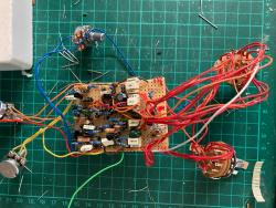 (I used the 2p6t in the exapmles to switch between 6 clipping options like the Pharaoh, I used the 4p3t to have 3 settings that flip between cap- changes at 4 parts in the circuit.) |
«
Return to Open Chat
|
1 view|%1 views
| Free forum by Nabble | Edit this page |