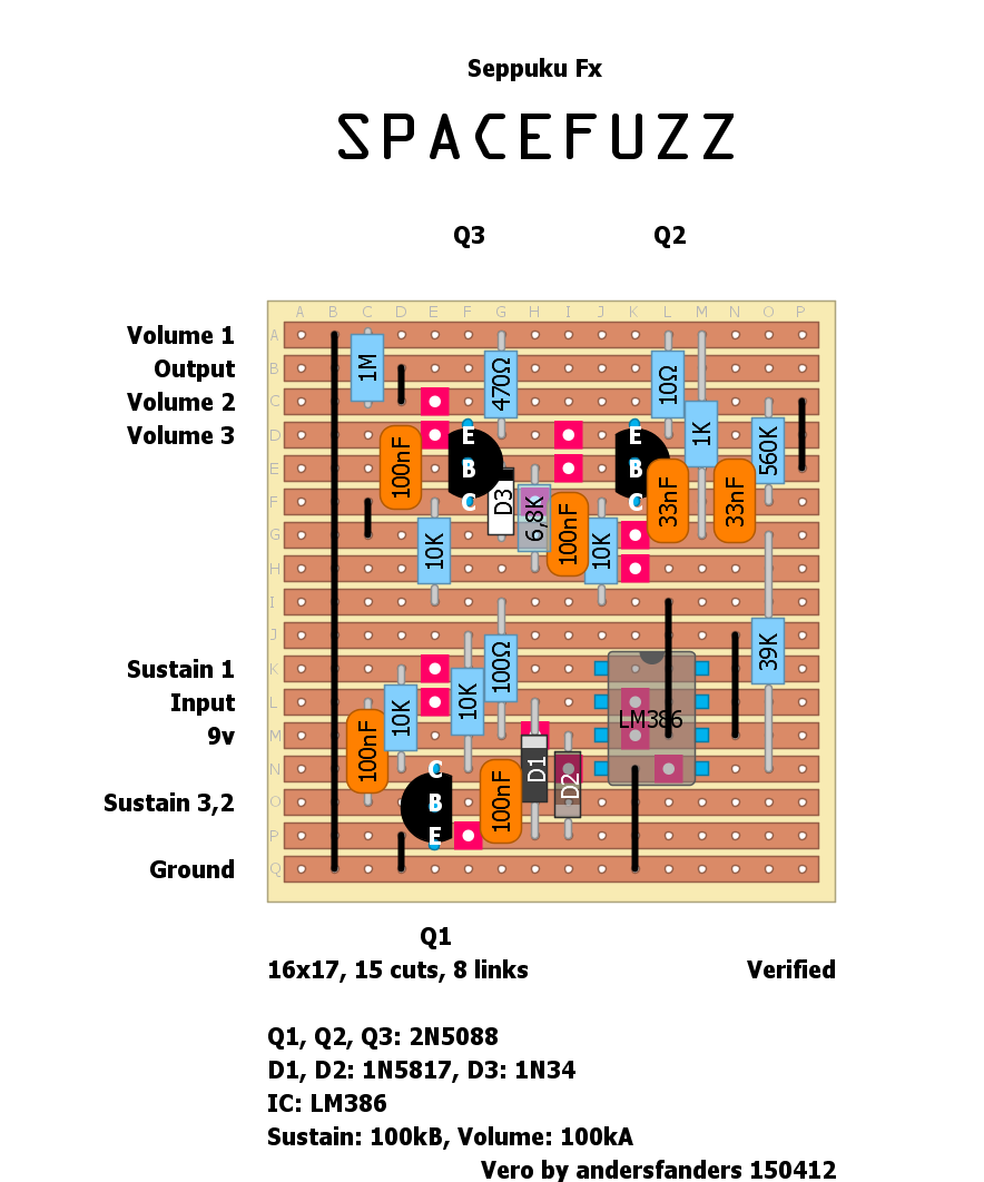
|
This post was updated on .
|
|
Thanks. With any luck I'll have it built in a day or two. I've been looking for some low knob count circuits.
Give a man a match and he'll be warm for a day.
Set a man on fire and he'll be warm for the rest of his life. |
|
In reply to this post by anders
Nice one :) Good job!
check out my building blog at www.parasitstudio.se
|
|
In reply to this post by anders
I built this up today. Although it works, the hiss is ungodly. I checked over at FSB and saw that others found it the same way. In your build are you experiencing this? I've found that by bridging rows H and I the noise drops quite a bit and there is still plenty of signal. The down side is that I think it changes the nature of the attack. I'm going to give it another tinker in a bit but I couldn't find any discrepancies with the layout when I was troubleshooting.
I'm open to ideas and will post up if I figure out what I did wrong.
Give a man a match and he'll be warm for a day.
Set a man on fire and he'll be warm for the rest of his life. |
|
I was mistaken, it was rows J and K that I linked to suppress noise. The link is made on the far left in column C. The attack issue I was hearing is what I believe to be the advertised touch sensitivity. By hitting the strings more gently the the attack seems faster while heavy single notes swell.
Anyway that's what works for me. I plan to get started on the octave drone next
Give a man a match and he'll be warm for a day.
Set a man on fire and he'll be warm for the rest of his life. |
|
Yes, my build is hissy too, lower gain trannys seems too reduce the noise but also sustain. Thanks for the tip about the link, I'll try that
.
|
|
I don't know what the hell is wrong with me. My link was made at column A, connecting rows G and H.
Sorry.
Give a man a match and he'll be warm for a day.
Set a man on fire and he'll be warm for the rest of his life. |
|
I used a KN386N-1 just like the original but the folks over at FSB recomends a LM386N-3 to solve the noise issue. I also replaced the germanium diode with a 1N4148 and it sounds much better to my ears, fuller, heavier and brighter.
|
|
In reply to this post by anders
No luck on the verified page so can someone help,
i've had the Bits all waiting for weeks now. Its easy im sure, but I dont want to Guess wrong... On the verified version on this site(Seppuku Space Fuzz).. Where does the 'negative side' wire from the LED go to? |
|
The negative leg/cathode of the LED usually goes to to a lug on the footswitch which is grounded when the effect is engaged which completes the circuit and lights up. You can use a variety of different methods (google "3PDT footswitch wiring/schematic") but there are a few versions that connect ground to the central common pin of one pole and use that pole to either light the LED when on, and ground the input to the effect circuit when in bypass to reduce the potential for unwanted oscillation. Some versions ground both circuit input and output
|
|
The bit that I am not confident about is where to put the wire from the LED on the board.
In the offboard wiring diagram I posted there are four connections: Input output 9V Ground But for the Space Fuzz Circuit there are five: Input output 9V Ground LED Where do I connect the LED wire? P:S Thanks for responding I was beginning to think I had a bunch of bits with no home. Matt. |
|
Matt If you look at the off-board wiring page you'll see that there is a wire from +9v through a resistor (CLR) to the +ve leg of the LED. The negative leg of the LED then connects to the switch and runs to GND. Sometimes folk like to put the CLR onboard. This means they use the +9v already supplied to the main board and mount the Current limiting resistor on board as well. It just means that you have the supply wire from the board to the +ve leg of the LED and run the -ve led to the switch as normal. It's just a neater way of doing things. You could leave RLED and the LED+ wire out of the layout entirely and wire the offboard as you normally would. Hope that helps |
|
Thanks for your response much appreciated.
Just to Clarify so Im sure I understand correctly: I can completely miss out RLED and the LED+ wire (so that I have only four wires) and connect the offboard wiring as normal? There is a break in the Vero under the RLED - do I miss this out? And do I need to add any further wiring to make the board a circuit because I have taken out the Resistor, or just simply remove it and it will work OK? Thanks Again Matt. |
|
yeah just leave out the RLED and the LED+ wire, i'd leave the cut where it is. You will still need to wire the led and CLR to the switch as it appears on the standard off board wiring (main page) if you want the LED to come on when you engage the effect. If I were you i'd leave the RLED on board and wire the LED to the board as it shows in the layout, it's a much neater way of doing things,but ultimately it's up to you. Good luck |
|
Fella,
if you feel good tomorrow, Its because I'm sending you a 'Big soul shakedown Thank you.' I agree it is better to have the LED on the board, So much so that I started to use a PCB that fits on the stomp switch from Tayda, which makes life easy and includes an RLED and LED (Hence my concern about the 5th wire) But I've got it now- and much appreciated. Thanks again. Matt. |
| Free forum by Nabble | Edit this page |
