Spaceman Effects Mercury IV - Verified

classic Classic list List threaded Threaded
13 messages Options
Reply | Threaded
Open this post in threaded view
|

Spaceman Effects Mercury IV - Verified

anders
This post was updated on .
A very cool design as usual from Spaceman Effects a "Harmonic Germanium Booster",  It's a bit my paygrade to explain how the circuit works but it looks like a discrete op amp design with a PNP germanium transistor in place of a PNP silicon. There is also a section that looks familiar to the octave section of the Superfuzz but with J Fets combined with a Mu Amp stage for biasing.

*Edit*
Now verified with a corrected layout. Thanks again to brazdj for build info and verification.


Here is the schematic providied by Dino.

Reply | Threaded
Open this post in threaded view
|

Re: Spaceman Effects Mercury IV

PMowdes
You got in this nice and quick 😀

I have the transistor info, I'll post it up later today.  I'm surprised nobody has jumped on the nebula yet, I posted a link to the schematic a few weeks back.  We also have the Titan ready to go as well.
Reply | Threaded
Open this post in threaded view
|

Re: Spaceman Effects Mercury IV

anders
Way cool about the Titan, looking forward to see whats under the hood.

As for the Nebula, I've done some attemts but failed miserably  Thathat thing is a heck of a circuit to do on vero. lot's of connections and those two current mirror SMD chips. I will try again but I suspect someone else will do a better job on this one*cough alex cough*.
Reply | Threaded
Open this post in threaded view
|

Re: Spaceman Effects Mercury IV

Mulekicker
Ooh! Titan, yes please!
Reply | Threaded
Open this post in threaded view
|

Re: Spaceman Effects Mercury IV

PMowdes
In reply to this post by anders
Reply | Threaded
Open this post in threaded view
|

Re: Spaceman Effects Mercury IV

Sensei Tim
In reply to this post by anders
that's a lot of transistors.
Reply | Threaded
Open this post in threaded view
|

Re: Spaceman Effects Mercury IV

Mulekicker
Yeah, I get nervous whenever I see more than 2 jfets.
Reply | Threaded
Open this post in threaded view
|

Re: Spaceman Effects Mercury IV

anders
In reply to this post by PMowdes
Gotcha. Layout updated with correct transistors.
Reply | Threaded
Open this post in threaded view
|

Re: Spaceman Effects Mercury IV

digi2t
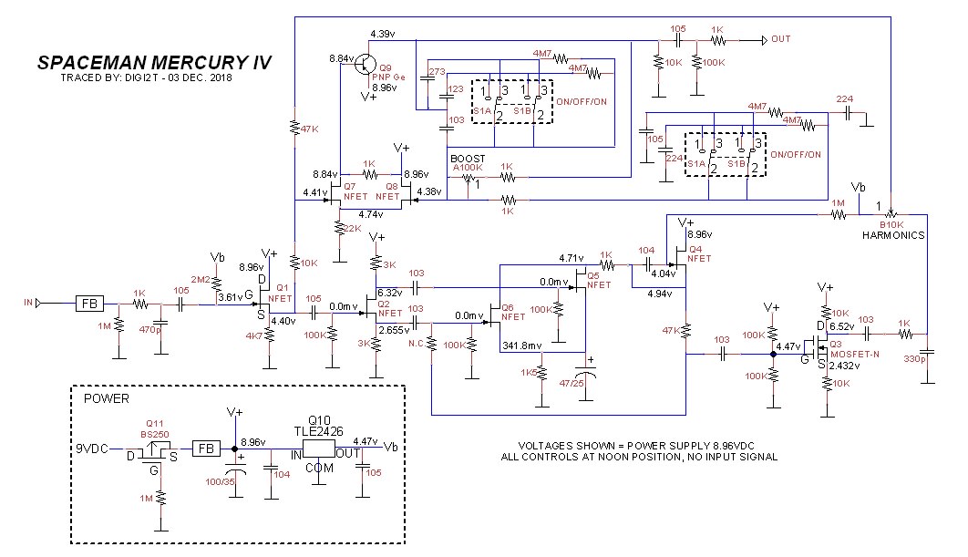
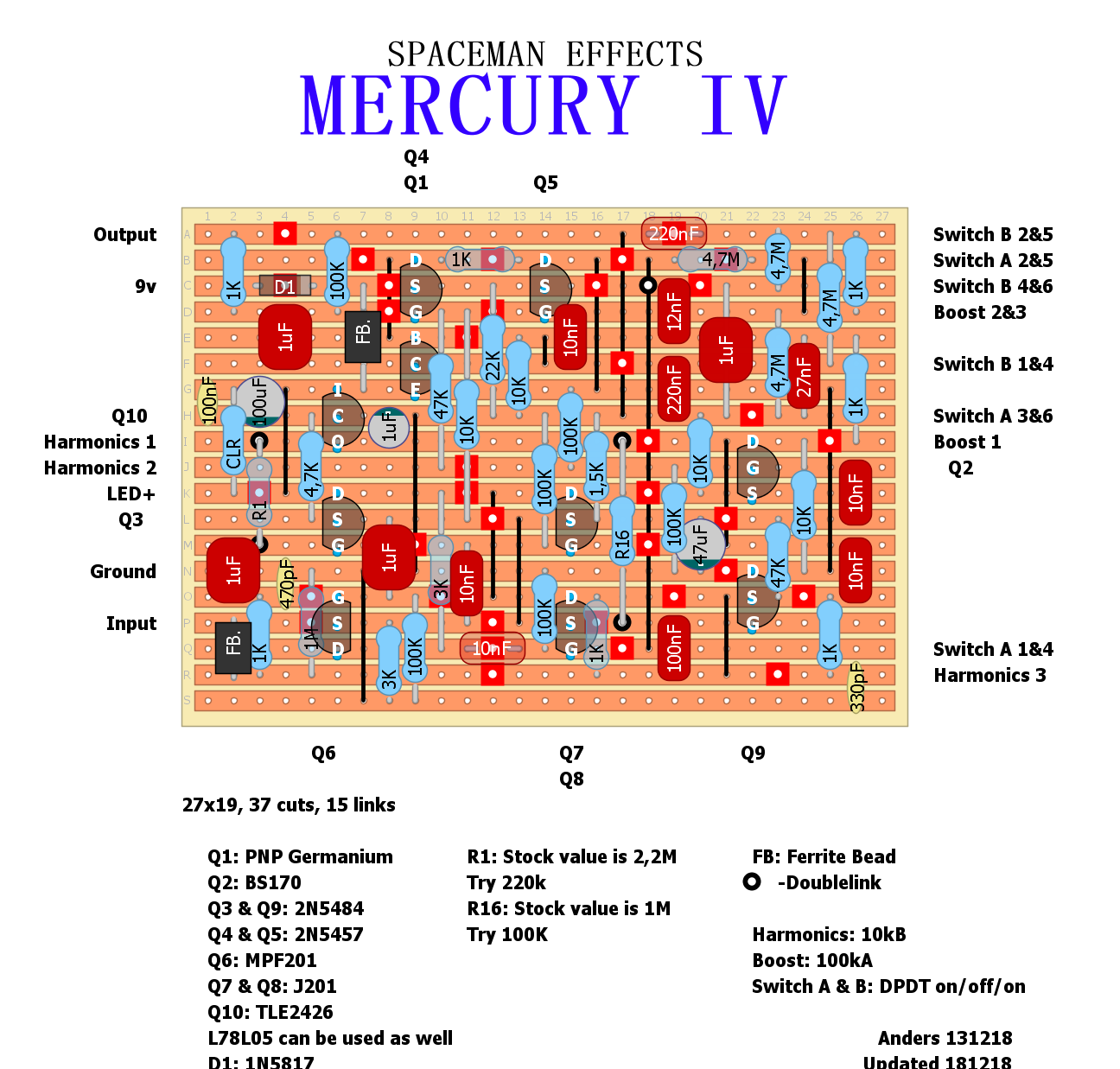
For reference, here is the original trace with the voltages. This will help you get into the wheelhouse where jfet selection is concerned. For the mosfet, I found that the BS170 landed closer than the 2N7000 voltage wise, but they sounded pretty much the same. Whatever Phil has on his schematic as spec'd jfet or mosfet is what got me the best results.

For the PNP Germ, 75 to 85 hFe, less than .1mA leakage works fine. I used a Russian MP20B, voltages are spot on. All voltages on the breadboard are at +/-10% or less.

As for the Harmonics control.... it's VERY subtle. If you want to hear it working, crank your amp, and just twist the knob back and forth. You should here the upper frequencies (slight hiss) come in as you go to max.

REMEMBER!!! THIS IS STILL NOT VERIFIED. ONLY TESTED ON THE BREADBOARD.

Reply | Threaded
Open this post in threaded view
|

Re: Spaceman Effects Mercury IV

brazdj
Hello and thank you for the contribution(s)!

I am still new to all of this, but I think that the Q6 mpf201 should be an mpf102 based on Dino's schematic. A 201 is a mosfet, whereas a 102 is a jfet.

I'll be soldering this guy soon (maybe tonight) and hopefully a verification follows!
Reply | Threaded
Open this post in threaded view
|

Re: Spaceman Effects Mercury IV

brazdj
VERIFIED! Alright I verified this with the following changes:

- The output portion of the vero layout is not correct. I built it as is, so I had to rig it to work. here is what you do: Move 1uf at E2,C2 down to F2,E2. Move 1K from F7, C7 left and up to E1, C2. Connect output to C1, not D1.

- I used 2N5458 instead of mpf201

- I used J201s instead of J102

- I used an L78L05 instead of the TLE2426

- I used spdt on/on/on instead of dpdt (I am not sure why they are dpdt in the schematic/design)

- PNP germ hfe ~=85

- I used a 220K resistor from Vb to Q3 gate instead of 2.2M. I was dropping too much voltage with the 2.2M.

- I used a 1000K resistor from Vb to Q9 gate instead of 1M. I was dropping too much voltage with the 1M.

- Q4 and Q5 were cycled to get as close to matching gate voltages as possible. 4.7 and 4.5... good enough for me.

It sounds pretty excellent, the harmonics definitely "bloom".
Reply | Threaded
Open this post in threaded view
|

Re: Spaceman Effects Mercury IV

anders
Awesome! I'll update the layout and add your suggestions later today.
Reply | Threaded
Open this post in threaded view
|

Re: Spaceman Effects Mercury IV

digi2t
I concur with the number error. I got my 102 ans 201 mixed up. I meant to say MPF102 and J201.

The TLE2426 is a rail splitter, and just a fancy way to create a voltage divider. You could just as easily use two 10K resistors between V+ and ground to get Vref.

As for the DPDT switches, since Spaceman boards are supported by the pots and switches, I can only assume that this creates a better mechanical support for the board. SPDT switches are fine.