Stripboard/Breadboard Interface for beginners
Stripboard/Breadboard Interface for beginners
|
Hi folks
After building 10 pedals and dumping 2 non functioning ones, I finally put together this wee test rig ala Beavis Audio. 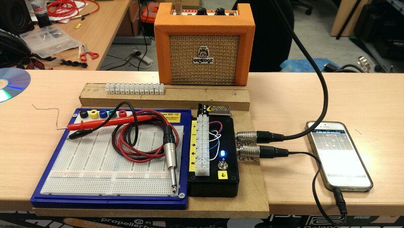 Interface with In/Out jacks, 3PDT toggle and LED wired ala Marks Input Ground technique. Breakout box on top for connecting to Strip/Breadboard Audio Probe with DC blocker in Jack. Amplifier at the ready and my phone as a signal generator. Thinking of recording some DI'ed electric guitar riffs/chords/solos and loading into phone to play on loop while I tweak/debug Highly recommended for beginners (like myself) If i were to change 1 thing.... solder croc clips to the breakout terminals. That way I wouldn't have to lift a screw driver every time I got to work. Great community here. Cheers |
|
That's really cool.
One thing to consider: the output impedance of your phone is probably not the same as your guitar. Some pedals care a lot about that (Cot-50, fuzz face, etc.). For debugging, this is no big deal, but if you want to tweak values on any pedal that sees the guitar directly, you might consider making a circuit with a buffer feeding a pickup simulator to go between the phone and the input. This will give you a more guitar-like signal. (This works well for re-amping in general, for those who like to record a dry signal and experiment with different amps/effects. Kind of like an analog version of Amplitube.) Watch the input levels too. Passive pickups put out a pretty small voltage signal. |
Re: Stripboard/Breadboard Interface for beginners
|
Ah! Good point. I've a few transformers laying around from a reamp build. Might try to put it on another switch(es) to use when plugging in the phone, then flick to bypass when plugging in a guitar.
The thought of constantly strumming a guitar while working would put me off altogether. Cheers for the insight. |
|
I use a similar rig for testing new builds. I've stuck a set of speaker terminals on mine. Makes it very easy to use:
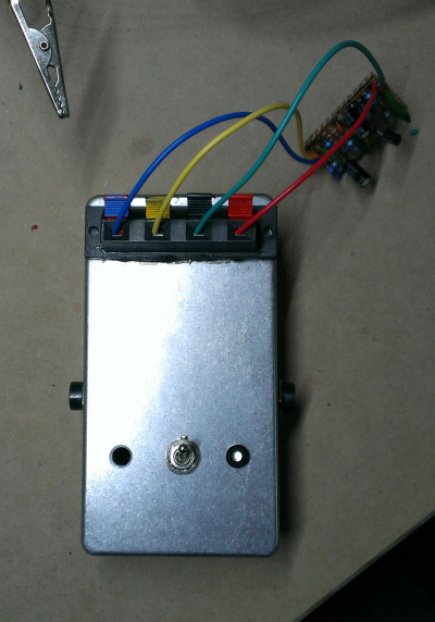 You can get the speaker terminals here |
|
I'm interested in building something similar to these test rigs. But I always wonder, don't the circuits need the pots attached in order to test them?
Adstrum's circuit doesn't seem to have any pots attached. Does that circuit work with just the power, input and output hooked up? |
Re: Stripboard/Breadboard Interface for beginners
|
I tend to use Alpha pcb pots (pins for lugs). On a breadboard these slot in nicely over a 5 row span. If you look at the bottom of my breadboard you can see rows running vertically. This allows me to put all my pots on the bottom of the circuit for easy access when tweaking. I just jumper from the circuit to the relevant pot.
When I'm happy I then transfer all to stripboard, wire in all pots but connect the rest to the breakout box and test the board for errors. If all good I start boxing. I'm only new to all this but I can deffs say this interface is great tool. Go for it! I've already started retrofitting a transformer AND Adstrums speaker terminals. |
|
Not even close to yours, but here's what I have.
Got the idea last week from this http://pcb.delyk.com/utility-boards/9-effects-tester-kit.html and decided to make one for myself. You have to actually build the vero first, and then try it. It just includes all the wiring except the board and any pots/switches. Here is a pic of mine (kinda ashamed after all the neat things you all posted) 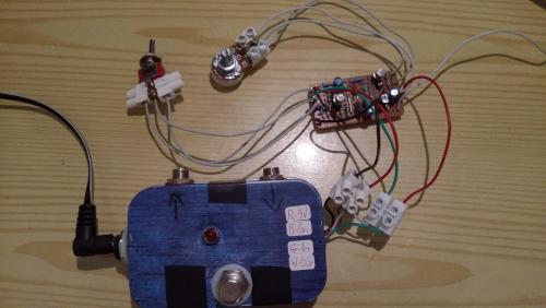 Here you can see it hooked up, and you can also see how I test pots and switches before soldering. Also includes a humminator (search the forum for it), and finally here's how it's wired. 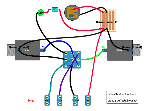
|
Re: Stripboard/Breadboard Interface for beginners
|
Nice job! What are the parts called that you are using for the pots/switches and where did you get them.
I'll want to use them in my setup. I tried looking at "terminal blocks" in Mouser, did show anything like that.
Yeah, 220, 221. Whatever it takes.
|
|
Well, in Greece we call 'em "Clemens", although no one seems to know why. Searching google I found them in the general "connector blocks" category
They just look that way because three of them won;t fit together on the lugs, so I strip the middle one from its cover. |
Re: Stripboard/Breadboard Interface for beginners
|
Any hardware or electrical retailer should have them too. Terminal block; terminal strip, connector block, various names to try.
I have some small sized stuff that can fit 3 side by side on a standard alpha pot. I just trim off the excess plastic at the entry points. 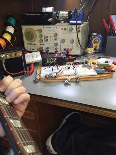
|
Re: Stripboard/Breadboard Interface for beginners
|
That's such a sweet little station you've got going there.
Through all the worry and pain we move on
|
Re: Stripboard/Breadboard Interface for beginners
|
This post was updated on .
In reply to this post by Ciaran Haslett
Took awhile but I finally finished my new Test Box based on Miro's V2. Only I added a few extras. It can now do the following...
Supply a test build with 9V or 18V (Zach's switchable Charge Pump) Input a simple 555 square wave for debugging/probing purposes (my own layout below) Switch in a simple JFET Input Buffer Switch in a simple JFET Output Buffer Connect/switch in an Audio Probe Hook up Test Build without any tools (finally!!!) Finished product 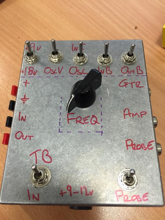 The switches top Left to Right. 9V/18V, Oscillator Power, Osc/In Jack, In Buffer, Out Buffer Bottom Main Bypass, Audio Probe Oscillator 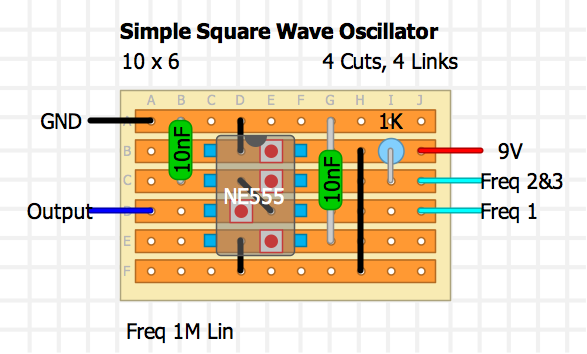 Wiring Diagram 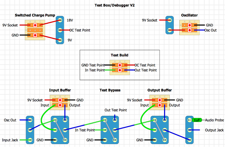 Haven't had a chance to use it yet but everything functions as expected. I was concerned the oscillator would bleed through hence the power switch for it. I wasn't concerned with LEDs but for anyone who may ask, just add a pole to each switch and wire an LED in the usual way. Hope all this is any use to someone. |
|
Administrator
|
very nice man. great ideas on how to take the test box to another level.
|
Re: Stripboard/Breadboard Interface for beginners
|
In reply to this post by Ciaran Haslett
I've spotted an error on the oscillator. Output should come from Pin 3 not from Pin 2. I drew this from memory and misplaced it sorry. I checked my build this morning and confirmed that everything else on the layout and wiring diagram is correct. I'll update the OSC layout tonight when I get back to the house.
|
Re: Stripboard/Breadboard Interface for beginners
|
All now updated and correct....including some ghetto labelling. Tested it today on a Silicon FF build and friend was making. Performed great.
|
«
Return to Beginner's Corner
|
1 view|%1 views
| Free forum by Nabble | Edit this page |

