Superfuzz/Wattson EFY-6 - Transistor Question.
|
I'm just getting my parts together to build the Wattson Classic Electrons EFY-6, and I noticed quite a few people using matched lower gain 2N2222 transistors (along with the suggested higher gain 2N5088's).
I'm for sure going to spend a million hours experimenting, but as far as the layout goes, it recommends using 2N5088 for Q1-Q6 (with Q4 and Q5 matched). For those who have built this (Travis, if you see this, I'm sure you can direct me, after all you are the reason i'm on this path!!!), should I be using the lower gain 2N2222's in the Q4 and Q5 position? Also why the substitution of low gain trannies instead of using all higher gain like the layout suggests? Any other higher gain trannies I should dig out besides the 5088's? Thanks!!!! |
|
I would try all 5088 and for Q4, Q5 2N2222 matched
|
|
Administrator
|
In reply to this post by SeaWitch
First off, I’m not so much a Superfuzz DIY guru as I am a simple user of the Superfuzz. I’ve only built the FY-6 twice, but I got a Univox and Ace Tone which quelled my desire to clone
I want to say the layout was based on a schematic from GGG or somewhere like that where at the time they basically suggested 2N5088 for almost anything because it was a very common part I would start by following advice of DIYers here using lower hfe transistors like 2N2222 or 2N3904 for all positions As far as what to try you can try whatever NPN you’ve got. 2SC828 were used in the original and easily obtainable. Mind the pinout with those. My Univox has dome-topped transistors called C539 I believe which I have not found when I looked before. Not sure what is in my Ace Tone because the board is mounted upside down and the wiring is so beautiful I don’t want to disturb anything I pretty much have 2 suggestions for building this circuit, neither pertaining to your original question Use quality electrolytic caps with a long life span because there are so many electros in the audio path, the pedal will go bad if the caps fail Avoid using SIP sockets the transistors especially the cheapos sold from tayda etc There are several transistors in this circuit and personally I have had a bunch of build problems caused by poor connections in SIP sockets. Especially after experimenting with several different transistor types!! It’s much better to experiment on the breadboard and solder the transistors permanently to your build |
|
Oh man, I've been there with the worn out sockets (after swapping transistor after transistor). If I do use sockets, i make sure to drop a tiny blob of solder in each socket hole when I find my transistor of choice!
Thanks Travis, for the advice! I have a ton of 3904's so i'll be trying those first. And, I've yet to have a problem with a cap failing, but I'm curious, what are your electrolytic caps of choice? Also, do you feel the 1N34A is a suitable replacement for the NTE109 germanium diodes used in this? Thanks again! |
Re: Superfuzz/Wattson EFY-6 - Transistor Question.
|
What I do with sockets is break each pin out of the plastic. Then I stick em on to an unbroken row of sockets to line em up and hold them while I solder them in place. That way you have 3 little pins to swap trannies with and it's much easier to then solder them in place without worrying about melting the plastic. You just have to be gentle while swapping cause they bend easily.
|
|
Administrator
|
In reply to this post by SeaWitch
If you look at mouser for example the lifespan of electrolytic caps is listed
Nichicon makes a lot of good ones for not a lot of money. The lifespan of an electrolytic is supposedly doubled for every 10° below the rated operating temp, which is good news for a circuit like this that is never generating any heat. Regarding the diodes, I don’t know what type was used in the original. Mine has white diodes with red arrows and curly leads, I’ve never seen the same looking ones for sale. I always see people using 1N34A, 1N270, etc. There’s plenty of Russian Ge diodes worth a try as well. Generally I’m not a fan of NTE parts as they’re rebranded and inconsistent |
|
Transistor choice can play a huge role in how a Superfuzz performs. My opinion is lower gain is best, staying between 140 and 180. I haven't had the honor of peering inside an original unit yet, but I have had the time to acquire and measure plenty of old Japanese 2SC828 Q and R's, and I can tell you that they always tend to be on the low side of their published ranges. Why is this of any importance? Because the higher the gain transistors you use in this circuit, the splattier it will get. Sometimes to the point that striking a chord will cause a blast of hiss to emanate from your speakers before the chord appears. Another important point concerning the new production 2SC828 R's; they ARE NOT in the same gain range as the older original Japanese units. Will they work? Yes. But, you'll have to sift through a metric butt load of them to get a set that sounds right. Another tip; scouring flea markets and garage sales for old Yamaha console organs is your best bet to finding original 828's that will sound good. I scored one sitting on the side of the road for garbage day. Gutted it in short order, and pulled a lifetime supply of Q's and R's out of it.
Another method is to use a 4 transistor array chip, such as the TPQ2222, or TPQ3904, for the pre and post amplifiers. I think they also come under the MPQ prefix as well. They tend to be at the lower end of the spec'd gain scale, and you get four fairly close matched transistors to boot. The old B360DC chips work well too. For the octave section... If the octave up is just too crazy for you, and you didn't install a 10k balancing trimmer between the Q4/Q5 pair, might be a good idea to put one in (see; Unicord Superfuzz). You can then tweak the trimmer a bit to dial back the octave a tad. The trimmer is really there to manage mismatched transistor pairs, but it does offer the advantage of tweaking the octave output a bit. My weapon of choice here is the 2N2913 dual NPN can. It offers a matched pair of transistors in a single package, but sifting through a bunch of 2N2222's or 2N3904's to match up and audition for THE pair will work too. I'm just lazy. Besides, that big ole can looks bitchin' in there. Personally, I find the clipping diodes direct to ground compressed the sound too much, so lifting these a bit helps open things up, especially where chords are concerned. I like about 1K, but YMMV. I also replaced the 15K resistor on Q6 base with a trimmer. I've read the original units tended to be be in the 5.6v neighbourhood on Q6 collector voltage, so a trimmer helps dial this in, which also helps give the sound a bit more body. Again, this points to how low the gain of the transistors in the original units really were. Using a 2N2222, or 2N3904, will tend to show between 3 and 4 volts here. These tend to be my transistors of choice for a Superfuzz, so tweaking the collector resistor might be necessary if you really want to get fussy about it. So, here's my layout for it; This also includes a Scoop control, rather than the traditional scoop switch. As for the "LM394" chip, ignore that, and simply drop a 2N2913 into the respective pinout indicated on the vero. What does it sound like? |
|
Administrator
|
Hey Dino
I actually have some dual matched 2N2222. I think it’s 2N2223 but would have to dig them up to know for sure. I got them from our Bulgarian ebay supplier I want to say BG_manue or something like that. They are really cool and perfect for this circuit I need to recap this thing but hate to dig into it. It really is a thing of beauty 
|
|
Travis, some questions;
What are the transistors in there? Are they all the same? Could you post the transistor voltages, before and after the recap? That's just for my own archiving. I would appreciate it. If you want to maintain period correctness, try to stick with Mashushita branded caps. Light blue jacket preferable (hard to find), violet second choice (generally more expensive), or dark blue (most common). Having "Mashushita", or the squared "M" logo makes it more authentic. Here's a couple of examples; https://www.ebay.ca/itm/40pcs-For-Matsushita-SU-10uF-16V-5-11mm-Audio-Electrolytic-Capacitor-6221/221842907350?hash=item33a6de20d6:g:nWkAAOSwElxbwVOi:rk:1:pf:0 or; https://www.ebay.ca/itm/PANASONIC-MATSUSHITA-ECE-A16Z10-Qty-of-60-per-Lot-CAP-ELEC-10UF-16V-RAD/142356750861?hash=item21251fa20d:g:z98AAOSwSypY-dif:rk:13:pf:0 A more extreme method would be to carefully gut the original caps and embed (epoxy) new smaller package caps inside them. It's a method used by many antique radio restorers to maintain period correctness. There's a tutorial on the net about the process. It's a monks work though. |
|
Administrator
|
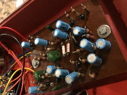
Thanks Dino. The transistors are simply marked “537Gd”. From what I can see they are all the same Regarding voltages, will do. Maybe I can find a component overlay for the board or I will just look at the schematic to figure which Q is which I was planning on using similar matsushita caps as you suggest, but I’ll take the easy way out and just save the original caps in a bag in case I or someone else wish to transfer the labels later |
|
This post was updated on .
Hmmm... just a cursory look, I think it might be this;
 Looking at the similar 2SC536 datasheet, the gain ranges for this series is listed here; http://pdf.datasheetcatalog.com/datasheets2/10/109739_1.pdf If your unit sounds really compressed and ragged, then the "G" gain range on the transistors makes sense. I don't know what the pinout is for the TO-106 Japanese transistors, so you'll have to glance at the schematic for figure that out. |
|
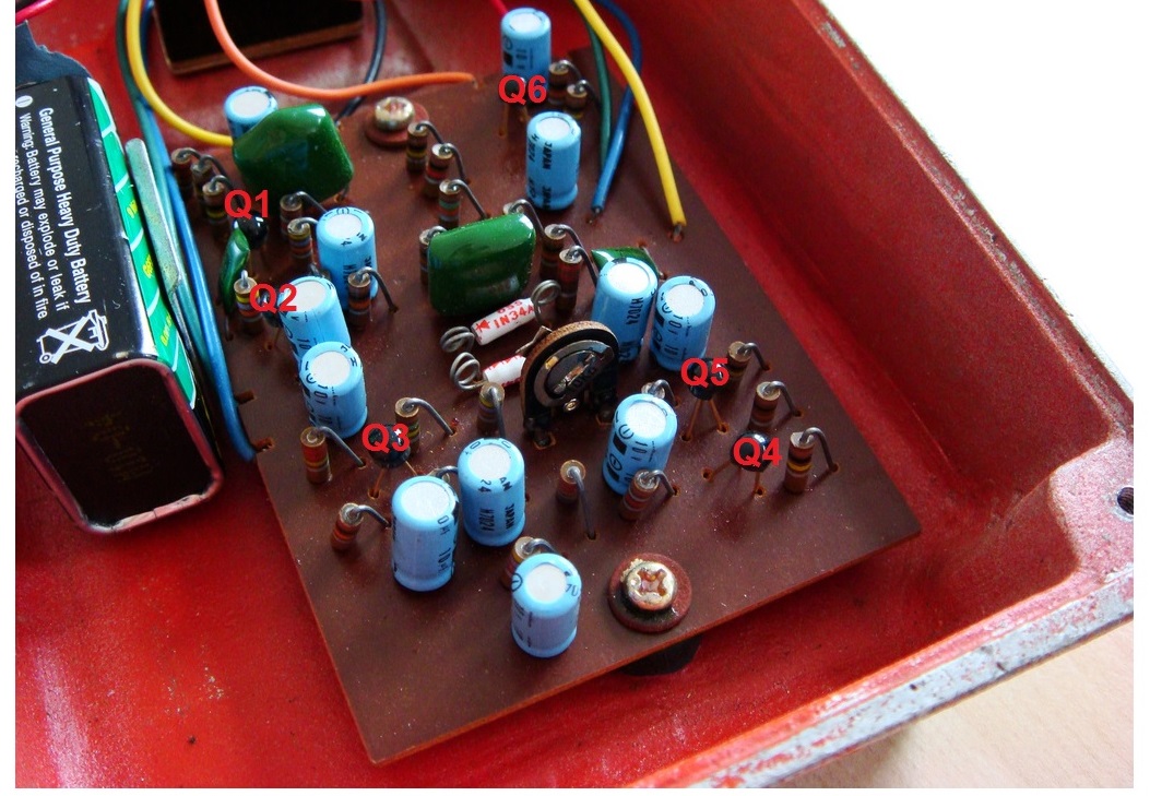
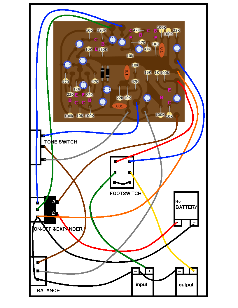
I saved this from the DIYstompbox forum I wanna say, can't remember. But it's the PigeonFX board, although it's without the trimpot it still looks pretty close and it has pinouts. It looks like those Qs are correct.
 I too have the big paddle Superfuzz in grey colour that I replaced the caps on, mine does not have a trimpot either. Funny thing is one of the green cap came off it's legs while I was in there, the cap was bone dry. Still haven't put the back lit on as the panel where the pots and tone switch are came loose. |
|
If I'm not mistaken, what you're showing there is the Shin Ei version of the Superfuzz. Architecture is essentially the same, but the board layout is different from the Univox / Unicord models.
|
|
Oh yeah, forgot that. I forgot to mention mine has C537EX in it, same TO-106.
|
|
Administrator
|
In reply to this post by digi2t
Actually it sounds really great, the only issue is that it can produce a noise right after my guitar stops that swooshes in and fades back out. I’m not sure if this is a cap issue, or if it’s being exacerbated by old caps, or if it’s purely a transistor selection issue The good news is that this is dependent on the fuzz/sustain control. I can turn the fuzz down a bit and still have a huge fuzz sound without noise issues. I can hear a couple parts in Live at Leeds where Pete Townshends Superfuzz has a little noise after the guitar just like mine can do. It basically sounds identical to that, if you use a similar setup and technique My FM-2 doesn’t do any noises at max gain. Probably hfe related It doesn’t have any issue sounding overly compressed |
|
If this is the case, I would try new caps, just as an A/B exercise. Pull all the electros out, but mark down where each one was originally. You don't want to perhaps upset any of the character that was due to differences in tolerances. I would take the time to also test the old ones with a cap tester, just to see if they've drifted out of tolerance. Plug in some new electros, and try it out. But, I think that what you are hearing is inherent to the circuit, and primarily due to perhaps the higher gain range of the transistors. It might also be exacerbated if running a boost in front. In the end, I think it's just the nature of your beast. If the old caps test good, I would put them back in.
Please record voltages with the original electros, and with the new. Using a stable power supply is best, using a 9v battery adapter clip. I have a Dunlop 9vdc walwart that is my shop standard. Anytime I take voltages, this is the PS that I use. It puts out exactly 8.97vdc. If you've ever studied any of my veros that state voltages, you see that "8.97vdc" printed on there. Back in 2008, member Solidhex was nice enough to publish his voltages from an orange model over at DIYSB. Here's the voltages; Battery voltage 9 volts dead on... C B E Q1 6.01 .66 .117 Q2 8.88 6.01 5.41 Q3 6.23 3.27 2.72 Q4 3.1 1.7 1.11 Q5 3.1 1.67 1.11 Q6 5.75 .98 .361 |
«
Return to Open Chat
|
1 view|%1 views
| Free forum by Nabble | Edit this page |


