TRACED...Zvex Fuzzolo. But I need help with verification.

classic Classic list List threaded Threaded
7 messages Options
Reply | Threaded
Open this post in threaded view
|

TRACED...Zvex Fuzzolo. But I need help with verification.

Ciaran Haslett
This post was updated on .
First time attempting anything like this so be gentle

I couldn't find a schematic for this in all the usual places so I got a lend of a friends and thought I'd try my hand at reverse engineering it

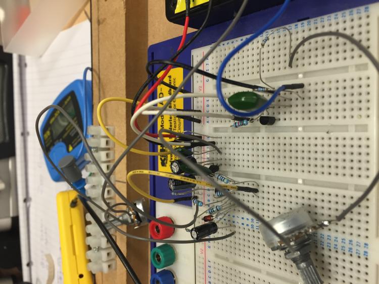
I worked through it and all went well until I got to the MOSFET.  The pots were on a second level PCB sitting over this section and I didn't have the stomach to unsolder 14 header pins on a pedal that wasn't mine.  The boards are dual layered with quite a few vias making for some head scratching moments but I soldiered through.

Anyway....

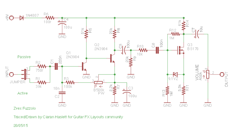
As you can see...the first 3/4s of it are basically a Mastotron with some pots replaced with fixed resistors or removed altogether.  So far so good.

Now the trouble begins.  There's a BS170 with a zener diode (couldn't identify the model..I could only make out "39B" printed on one side) that seems to be tied to the gate and source.  I did a bit of research and it seems common to tie the drain and source together rather than the gate and source for clipping...if that's what it's even doing here!

I'm 90% sure the rest is fine but again this is my first trace....hell its the first time I even opened Eagle to draw the schematic!  Which is why the pots are trimmer symbols!

So I'm calling all breadboard warriors!  Anyone have an hour to spare and verify/correct this?

I'm away for a long weekend tomorrow so I won't get a chance to have a go or answer many questions you may have.  I figured if I just put this here, you lot can do the dirty work

Oh and for the purists...

the 750r on the input was a 5% carbon film resistor while the rest were metal film 1%
The 10uf electro was 20% while the rest were 10%

Cheers folks

EDIT:  Schematic updated to correct values and VERIFIED
Reply | Threaded
Open this post in threaded view
|

Re: TRACED...Zvex Fuzzolo. But I need help with verification.

nocentelli
That looks fine, just a woolly mammoth with no tonestack into a super hardon for more level. The source->gate zener is entirely appropriate, it stops static voltages zapping the mosfet, something zvex didn't know about or didn't bother with on the first runs of the SHO. Will try this weekend.
Reply | Threaded
Open this post in threaded view
|

Re: TRACED...Zvex Fuzzolo. But I need help with verification.

Travis
Administrator
In reply to this post by Ciaran Haslett
Awesome, can't wait till we verify this. I wanted to build this one since hearing the PGS demo

Thanks Ciaran!!
Reply | Threaded
Open this post in threaded view
|

Re: TRACED...Zvex Fuzzolo. But I need help with verification.

Ciaran Haslett
In reply to this post by nocentelli
You're absolutely right!  Had a quick read on RG Keens site regarding this kind of thing.  Learning every day.

And looking at the Mammoth schematic it seems I may have misplaced C6.  Looks like it should be parallel to C5 and R10, not in series.  And should it be 10n?

And R10 looks like it should be 10k and not 100r..which is possible.  It was really hard to see under the pots PCB.

I'll wait till someone tries the current layout before making any adjustments now.

Cheers folks.

And Travis....I've a pretty tidy vero layout ready to go as soon as someone verifies the schematic.  I'll be back at my computer Monday night so hopefully I get the "Good to Go" before then.
Reply | Threaded
Open this post in threaded view
|

Re: TRACED...Zvex Fuzzolo. But I need help with verification.

nocentelli
I think C6 is probably correct as drawn, though R10 may well be bigger (10k would make more sense). Here's my reasoning: In the mammoth, the parallel 10n cap is part of the tonestack, and accentuates the treble when the tone pot is over to the bright side. In the fuzzolo, there is no tonestack but there is that 20k to ground: I'm guessing it is there to reduce the level and act as a HPF to lower the bass content before the signal hits the mosfet - this will be more effective if R10 was 10k (R10 and R9 acting as the two resistances in a voltage divider volume pot set to "2/3 volume"). If C6 was in parallel with C5 and R10, there would be no DC blocking cap in front of the mosfet gate: This would put a 20.1k or 30k (if R10 is 10k) resistance to ground in parallel with R13, and would mess up the biasing of the mosfet gate.

If C6 is indeed drawn correctly as I suspect, 100n makes more sense than 10n which would thin out the bass a bit too much. It's on the breadboard now, and I'll try it out with a 10k R10 this afternoon.

Thanks for all your efforts to trace this!
Reply | Threaded
Open this post in threaded view
|

Re: TRACED...Zvex Fuzzolo. But I need help with verification.

Ciaran Haslett
Hi nocentelli

Did you have any luck with this?  I'll be back at my breadboard tomorrow to give it a go if you're busy.

And cheers for the explanation.  It makes much more sense when it's written down in black and white while following a schematic.  Again...learning every day so cheers for that.

Ciaran
Reply | Threaded
Open this post in threaded view
|

Re: TRACED...Zvex Fuzzolo. But I need help with verification.

Ciaran Haslett
In reply to this post by Ciaran Haslett
Got a bit of time today...

The resistor before the gate was indeed supposed to be 10k (thanks to nocentelli)

I've updated the schematic up top and I'll move this to Contributions.  Thanks again.