Trotsky layout on Vero?

classic Classic list List threaded Threaded
17 messages Options
Reply | Threaded
Open this post in threaded view
|

Trotsky layout on Vero?

jaredcohen
Hey all. My girlfriend isn't happy I discovered this site. I've pretty much been researching/learning/building for a couple weeks now... Oops...

I've become pretty comfortable with building the vero layouts, and I became intrigued by the Trotsky, which is only hosted here as a tagboard layout. So I thought, "Let's see if I can turn it into a vero."  The only other vero "Trotsky" I could find on the internet doesn't match the schematic, so it wasn't very helpful to double-check my work. I was hoping you guys might be able to take a look at the layout I made and see if I've got things right.

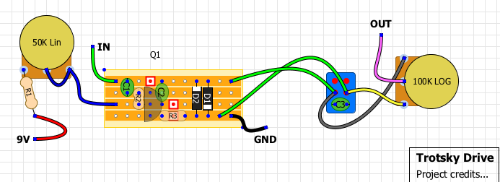
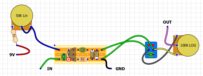
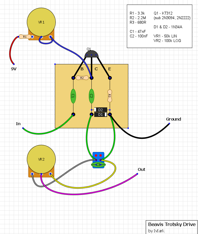
This is the original tagboard posted on this site:


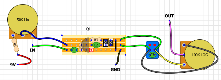
And here is my vero layout:


If I'm close, any advice or pointers are greatly appreciated.  If I'm WAY off, please feel free to let me know and I'll go back to my electronics book and try to learn some more. I'm perfectly happy having to do this 10 or 20 times to get it right.

That said, if I've got it functional but there are things I can/should do to make it more "proper" or more efficient, please let me know.

Thanks!
Reply | Threaded
Open this post in threaded view
|

Re: Trotsky layout on Vero?

jaredcohen
Sorry, I guess I should've linked to the original schematic too: http://www.beavisaudio.com/schematics/Images/Beavis-Audio-Trotsky-Drive-Schematic.png
Reply | Threaded
Open this post in threaded view
|

Re: Trotsky layout on Vero?

Dave
In reply to this post by jaredcohen
Hi Jared,
I'm afraid your layout needs a bit of work, mainly because you have things connecting to things they shouldn't. Take for instance the input, in the original the input connects to the transistor by passing through c1 whereas in yours it will just go straight along the strip, connecting directly to the transistor. Have another look at the schematic and make sure that each component connects with what it is meant to. Sorry for the bad news but hopefully you'll understand why it wouldn't work as is.
Thanks
Dave
Reply | Threaded
Open this post in threaded view
|

Re: Trotsky layout on Vero?

jaredcohen
Thanks Dave,

I feel like an idiot. I had a few beers and thought I'd figured everything out. I think the hardest part conceptually was/is that the signal is going to hit the entire strip at the same time, not go left-to-right like it does in my head. Thanks for making me realize that. Back to the drawing board!
Reply | Threaded
Open this post in threaded view
|

Re: Trotsky layout on Vero?

Dave
No worries, once you start to think the right way it gets a lot easier. Let's have a look when you do your new layout and see if it'll work.
Cheers
Dave
Reply | Threaded
Open this post in threaded view
|

Re: Trotsky layout on Vero?

jaredcohen
In reply to this post by jaredcohen
Okay, I stepped away from this for a while, but I think I've got a final version of the Trotsky on vero. Just wondering how it looks to you guys? I'd love a thumb's up before I take the time to build it, but it's small, so I might just go ahead and do that.

If you see anything that looks wrong, please let me know. Thanks!

Reply | Threaded
Open this post in threaded view
|

Re: Trotsky layout on Vero?

jaredcohen
Built it. Audio dies immediately. Probed it, there's no audio on the backside of C1, so it's dying as soon as it hits C1. Leads me to think something is grounding out, but I can't see how C1, R2, or the base of Q1 would be hitting ground.  I don't have any KT312, but I tried with 2n3904 and 2n2222. Same result.

I realize the cut after C2 is unnecessary, since nothing else happens on that track, but that shouldn't matter. I'm stumped.
Reply | Threaded
Open this post in threaded view
|

Re: Trotsky layout on Vero?

induction
The pinouts for 2n3904 and 2n2222 are different from KT312.
Reply | Threaded
Open this post in threaded view
|

Re: Trotsky layout on Vero?

jaredcohen
Thanks Induction. I should have mention to ignore the physical representation of the transistor. I had to align it left or right in DIYLC.  From top to bottom, the pins are C-B-E.  That's how I put the respective transistors in the breadboard as well.
Reply | Threaded
Open this post in threaded view
|

Re: Trotsky layout on Vero?

induction
Maybe I'm misunderstanding you. If the pins are c-b-e from top to bottom, then you're feeding the input to the collector, taking the output from the base, and attaching the power supply to the base. Your layout looks ok if the pins are b-c-e from top to bottom. That would require you to twist the legs.
Reply | Threaded
Open this post in threaded view
|

Re: Trotsky layout on Vero?

jaredcohen
You're exactly right, somehow the pinout of the transistor, and the pinout I was using in my head, are different. And no matter how many times I looked at the two, they looked the same. After about the 10th time reading your post, without understating why you were saying it, the lightbulb went on.  I'm an idiot.

I hate when you get too close to things and can't see the simple parts.  I'll give it a shot with the pins twisted. Thanks for your patience.
Reply | Threaded
Open this post in threaded view
|

Re: Trotsky layout on Vero?

jaredcohen
Well when you open your eyes, things are a lot easier.

This one is set up for the 3904 pinout, just in case anyone else wants it, and it seems to work. Sounds crunchy. On the breadboard I haven't hooked the bright switch up (it's just coming off the diode to output right now), but I don't see any reason that won't work as shown

Thanks so much for your help, induction.

Reply | Threaded
Open this post in threaded view
|

Re: Trotsky layout on Vero?

IvIark
Administrator
Looks good to me matey, nice job
Reply | Threaded
Open this post in threaded view
|

Re: Trotsky layout on Vero?

induction
In reply to this post by jaredcohen
Glad you got it working. It gets easier with every layout you finish, so keep it up.
Reply | Threaded
Open this post in threaded view
|

Re: Trotsky layout on Vero?

jaredcohen
In reply to this post by IvIark
I'm feeling very thick today. I breadboarded this a couple weeks ago and it worked. But I went straight out to an amp, no volume pot. Today I actually built it in Vero, and the Vol knob works backwards (i.e. maxed out there's no volume).  Wired the pot up the other way around (switched lugs 1 and 3) and that gives me no volume at all. That makes no sense to me... Any ideas?
Reply | Threaded
Open this post in threaded view
|

Re: Trotsky layout on Vero?

IvIark
Administrator
If it doesn't work at all the two solderings and one de-soldering may have damaged it.  At the end of the day there isn't too much that can go wrong with a volume control, as long as the input goes to 3, the output goes from 2 and 1 is grounded then it will do what is written on the tin.  If it isn't working bearing in mind the simplicity with only 3 connections to check, then it strongly suggests a faulty part.
Reply | Threaded
Open this post in threaded view
|

Re: Trotsky layout on Vero?

jaredcohen
Thanks Mark for the quick reply... that's actually good to hear. It's always nice if I can blame a component instead of myself! I'll give it a shot tomorrow with a different pot. Thanks again.