VGA Sync Generator

classic Classic list List threaded Threaded
11 messages Options
Reply | Threaded
Open this post in threaded view
|

VGA Sync Generator

skeletonghost
Crosspost from the contributions section:


It is from this Hackaday project: https://hackaday.io/project/9782-nes-zapper-video-synth-theremin/log/32282-vga-porching

It's for producing a VGA synch signal from discrete logic. So it could add video capabilities to your Guitar/CMOS synths!

The "sync" refers to timing signals that are generated to center the image in the frame. A VGA signal requires a H-sync and V-sync (horizontal/vertical) signals (timed to a specific frequency) to display properly. The RGB in the schematic have inputs where one could feed signals (like audio/guitar/cv) to create images. The quad switch is used to "porch" the RGB signals so they are only on during a specific period to display properly.
Reply | Threaded
Open this post in threaded view
|

Re: VGA Sync Generator

SonusFluxa
I'd like to get started working on laying this out (and ordered vga plugs a few days ago in anticipation), but have a question before I get started.

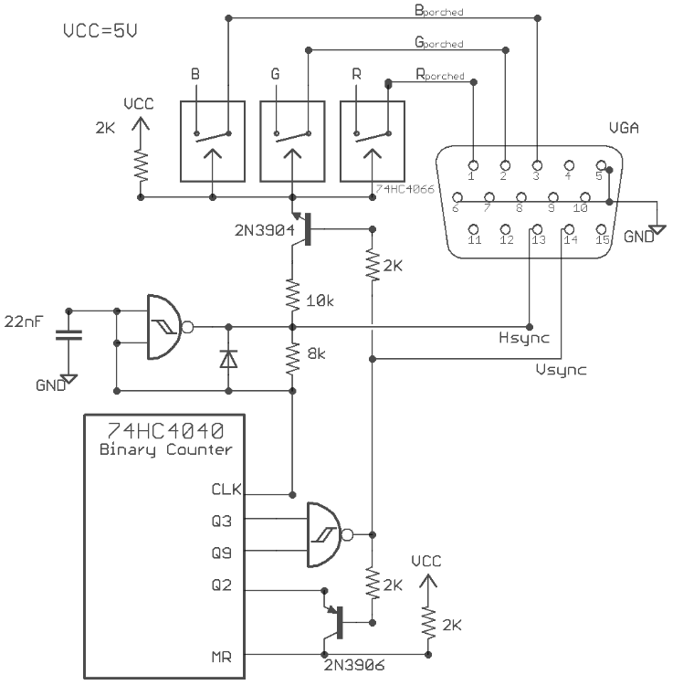
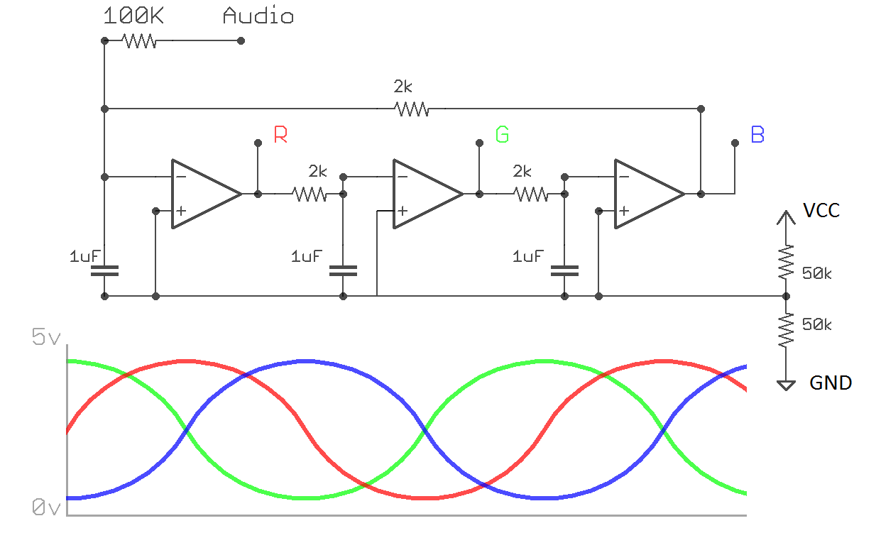
The schematic skeletonghost posted above seems like the basic part of the synth that creates the output. Would I then be able to attach this bit R>R, B>B, G>G to give it a bit more dynamic character? The audio looks to me like an input, and the rgb's outputs, but I could be mistaken.


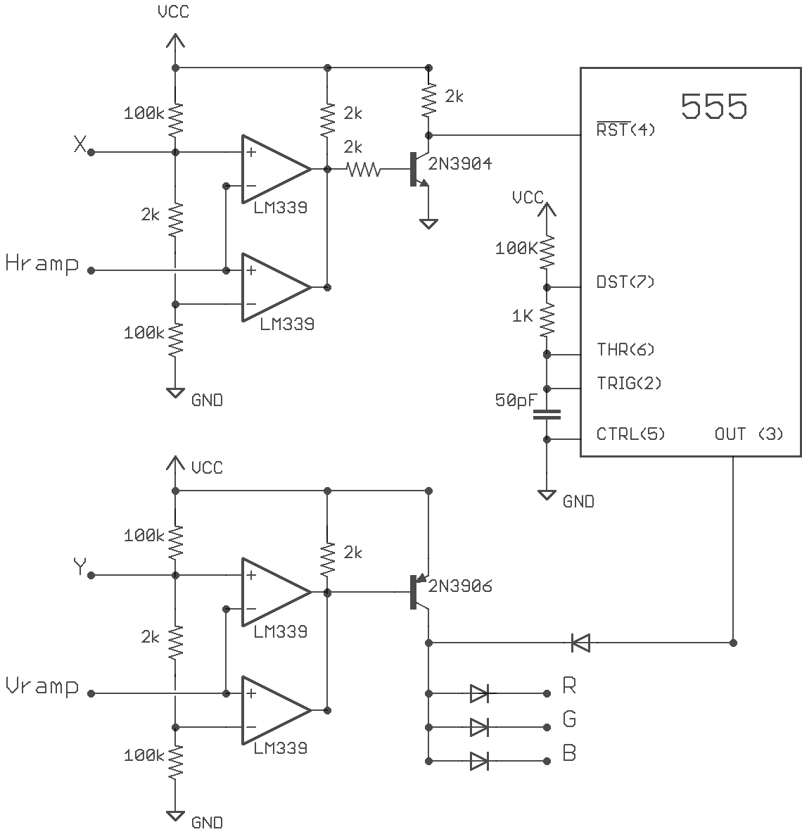
And then, what would be the way, if at all, to connect this bit? It looks to me like you'd be able to attach audio/CV outputs to the x, y, hramp, and vramp inputs, which would make it even more dynamic. Does this make sense, or am I missing something?


I apologize if this is a bit ambitious, but now skeleton has the gears turning, however slow and sticky those gears might be.
Reply | Threaded
Open this post in threaded view
|

Re: VGA Sync Generator

skeletonghost
This post was updated on .
Hey Sonus, where are these two new schematics from?

*edit* Ah ok I see, read further into the zapper project. I think the "Rainbow Phase Shifter" would be an awesome addition to the circuit as it introduces a native way to accept "audio level" input. If you are thinking of producing the layout could you add it as a daughterboard? That would be amazing!:

The circuit produces vertical rainbow bars because it phase-aligns to the Hsync pulses due to a sympathetic oscillation with the porching circuit. By applying audio I can push the oscillation out of phase and produce responsive patterns.
It is worth noting that VGA is expecting a 0.7v peak on the RGB inputs, so if your CV is 5v it will need to be stepped down before hand.  
Reply | Threaded
Open this post in threaded view
|

Re: VGA Sync Generator

SonusFluxa
They're part of the project log from the page you linked to from hackaday.
Reply | Threaded
Open this post in threaded view
|

Re: VGA Sync Generator

skeletonghost
Yep I did a bit of reading, I think these would both be awesome additions!
Reply | Threaded
Open this post in threaded view
|

Re: VGA Sync Generator

SonusFluxa
Right on. I'll read a bit more into it but if anyone has any insight into how they would be connected that'd be awesome. Might do them as seperate layouts for the time being.
Reply | Threaded
Open this post in threaded view
|

Re: VGA Sync Generator

skeletonghost
I assume the RGB connects in the "Rainbow Phase Shifter" would go to the RGB input on the quad switch in the first layout. The H-Ramp and V-Ramp would go to the H-Sync and V-Synch in the first layout
Reply | Threaded
Open this post in threaded view
|

Re: VGA Sync Generator

SonusFluxa
In reply to this post by skeletonghost
Here's my layout for the initial schematic posted. Not the most handsome layout, to be honest. The part that gets me the most is having that one damn wire by itself on one side.


This will be my first time working with video, so I'm not sure how testy it is with voltages. Like most of us, I use a 9v wall wart to power my projects, but the schematic for this listed VCC at 5V. I figure this is because he's using 74HC chips, whereas I'm planning on trying my luck with CD4XXX, which take higher voltages. In any case, I've got an untested 5V baby board that I plan on using for my synth stuff, taken from various castlerocktronics schematics, which could be useful for making sure it gets the voltage specified:


I'm still waiting for my VGA connectors to come in the mail, but hopefully I can test this out soon, and one of you can test it out in the mean time.
Reply | Threaded
Open this post in threaded view
|

Re: VGA Sync Generator

skeletonghost
Amazing! Thanks for this layout! I will try to build it within the next few weeks. Unfortunately I think you will have to use TTL chips of the 74H series as I don't believe the clock speed of CMOS will be fast enough to generate the timing frequencies needed. The distinction has a handy explanation in this document by Castlerock http://castlerocktronics.com/modular/articles/CR-006_-_Dual_Divider.pdf
Reply | Threaded
Open this post in threaded view
|

Re: VGA Sync Generator

SonusFluxa
You posted this as I was dropping the CMOS chips into their sockets. Not getting any video with The CDxxxx chips. My monitor goes into power saving mode.

I'm looking for the 74HC chips, and can find all except the 4093 online. If you have all the bits, I'll be curious to know whether it works for you. Also might have to mess around with the connections on the 4040, since it seems the pin counts start at either Q0 or Q1, and I couldn't find any indication for which he used.
Reply | Threaded
Open this post in threaded view
|

Re: VGA Sync Generator

skeletonghost
Another quick note, I mentioned this before: The RGB input is expecting a 0.7v peak. So if the input is being routed from something like a lunetta or other kind of synth the 5v CV signal will need to be stepped down with a voltage divider.