Voodoolab Superfuzz Diy
|
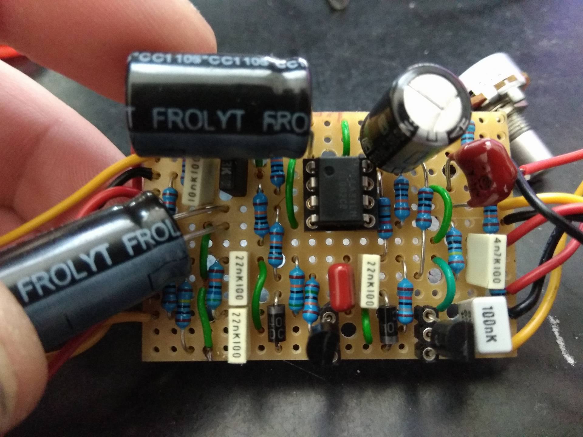
Hello there, I built the Voodoolab superfuzz, everything works fine (pots, volume, tone and resonance) but I find there's a lack of... punch !!!
Volume pot needs to be at max otherwise effect have no real presence. Attack pot have no real interest too unless I roll it up more than half Tone is very "muffy" when fully CCW (maybe is it normal ???) There are voltage measurements: MPS A18: C: 2.66 B: 0.51 E: ground 2907: C: 3.23 B: 2.66 E: ground TL062: 1: 4.53 5: 9.10 2: 4.54 6: 4.76 3: 4.53 7: 4.51 4: 0 8: 4.49 If anyone could be kind enough to help me /// it will be great to tell me where I'm wrong. My sunface BC108 works a way better and it's slighlty larger that a phone SIM Card !!! lol Thank you 
|
|
I'm not familiar with this one sorry. But let's assume that there IS something wrong.
Is that big ass can definitely 10pF??? If so then that might simply be how the circuit should sound...and you just don't like it! The Attack control works the same way as your guitars volume control...just an input level control to the entire circuit. You could try changing its taper to a "C" or remove it (you'll need to check the schematic) I've built enough "disappointing" circuits that I now breadboard everything before committing to vero. And welcome lad! 
|
|
Thanks for your answer.
I'm quite certain for the big ass caps value. "Quite" because it's difficult to check it on the shinny surface. What do you mean with "C" taper. I'm not very familiar with these terms. |
|
This post was updated on .
Two Superfuzz schematics are here: http://freestompboxes.org/viewtopic.php?f=7&t=449&hilit=voodoo+superfuzz and
http://freestompboxes.org/viewtopic.php?f=7&t=449&p=254952&hilit=+voodoo+superfuzz#p254952 They disagree on the orientation of the PNP 2N2907 which might be part of the problem. The transistor voltages also look odd to me. If you look at the resistors above and to the left of the MPSA18 transistor, there is a path for DC voltage from V+ to ground through R1-R2-R3-R4, 18K - 560K - 560K - 150K. When the MPSA18 is not conducting, this sets the voltages of both the base of the MPSA18 and the collector of 2N2907. It biases the MPSA18 - the base of a NPN transistor needs to be held above the emitter by roughly a P-N voltage drop (about 0.7 V) or it won't do anything. The voltage at the base of the MPSA18 should be 9V * 150 / (150 + 560 + 560 + 18) , so about 1.0 V. The voltage at the collector of the 2N2907 would be 9V * (150 + 560 + 560) / (150 + 560 + 560 + 18) = 8.9 V. However, when the MPSA18 is conducting, it should provide a low-resistance path that pulls these voltages down. In the extreme case that the MPSA18 pulled a lot of current through it, the path from V+ to ground is essentially R1 - R5 - MPSA18, and the MPSA18 is effectively zero resistance. So then the R1 - R5 junction is at 9V * 18 / (18 + 18) = 4.5 V. And the base of the MPSA18 is at 4.5 V * 150 / (150 + 560 +560) = 0.5 V. So that might explain why you're getting the base of the MPSA18 at 0.5 V, but it wouldn't explain why the collector of 2N2907 is less than 4.5 V, unless the 2N2907 is itself sucking the voltage down. To summarize, I'm a bit skeptical of both the vero layout orientation of 2N2907, and that the transistors are getting the right bias voltages. [Edit: I meant the resistors above and to the left of MPSA18 on the schematic, not the vero.] |
|
Administrator
|
In reply to this post by Jonalix
That's the same cap that I pointed out to you in the comments of the layout page
Looking at the pic sorta confirms my suspicion that it is the wrong cap. It appears highly unlikely that it is the correct cap. You should really give that some attention before spending any more time on this |
|
Thank you all for such investigation. I hope you're right about this cap, plus you're thinking both the same !!!
Like I said earlier I can't read no more the value on it. So we're talking about the cap on the top right ? Is that correct ? Thank you Travis I'll have a triple check as soon as I get home. Sorry for my English |
|
Administrator
|
Yes the red cap at the top right.
It should be a 10pf (picofarad .00001uf) that's probably going to be a ceramic or silver mica cap. They are extremely cheap if you need to buy one (or 100). Check ebay |
|
Administrator
|
In reply to this post by Jonalix
Also for future reference, the IC pins always numbered in a "U" shape like this
1 8 2 7 3 6 4 5 Or a 14 pin IC would be like this etc 1 14 2 13 3 12 4 11 5 10 6 9 7 8 |
«
Return to Debugging
|
1 view|%1 views
| Free forum by Nabble | Edit this page |

