Wampler Faux Spring Reverb help
|
Hi
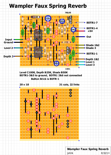
Currently building this as i have some spare BTDR-1H belton bricks which i bought by mistake. Can someone check the belton brick connection for me. I have a feeling its wired wrongly after looking at the datasheet but maybe i am wrong. The connection to 5v from the board seems to be connected to the Vcc rather than the Vin. Any help would greatly appreciated. Hoz 
"Red velvet lines the black box"
|
|
Still can't get this to work. Any suggestions?
"Red velvet lines the black box"
|
|
The brick connections are correct on the layout.
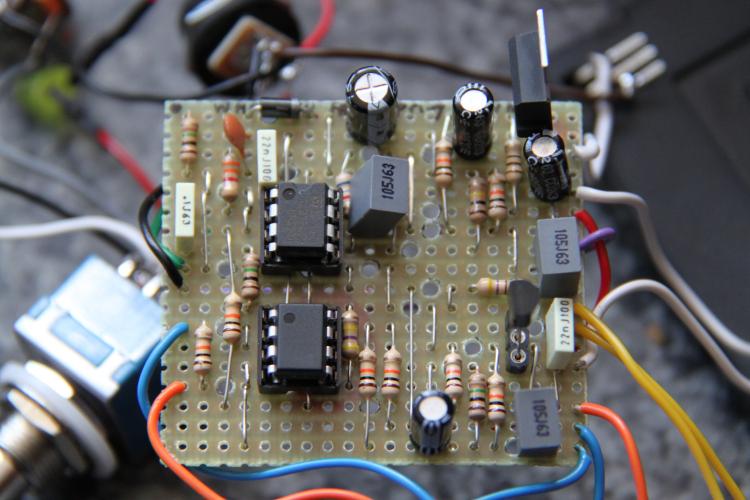
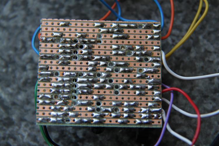
To help you troubleshoot we need to know what it's doing or not doing. Does the dry signal work? Does it work in bypass? What are you using for power? Did you correctly make all of those double links? Post some photos and we'll see what we can do: Hi-res closeups of both sides of the board, and shots of the all of the offboard connections. |
|
Thanks Induction. Photos of back and front. I have only connected link 5 from the brick to ground as the datasheet mentions you don't need to connect both.
  The voltages are well weird for the opamps and i am getting voltage at the ground pin of the 7805 Her are the voltages. Obviously i have checked for solder bridges etc. Also should mention that I am getting no signal coming through at all. top tl072 1. 0.79 2. 0.79 3. 0.27 4. 0 5. 0 6. 0.09 7. 0.81 8. 7.57 bot tl072 1. 6.99 2. 6.99 3. 0.78 4. 0.78 5. 0.96 6. 6.39 7. 6.93 8. 7.58 7805 I. 7.58 G. 0.78 O. 5.73 My tl072s are slightly different one is ACN after the other is CP not sure if that would make a difference though. Thanks again for looking.
"Red velvet lines the black box"
|
|
This post was updated on .
***ignore this post and look two posts down, instead***
The layout looks wrong to me. Referring to this schematic, pin 5 of the upper TL072 and Level 1 should both be connected to VD, not ground. VD is a voltage divider, basically a duplicate of VB. I suspect this was misread as V0 and interpreted to be ground. Try moving Level 1 to row 9 (from the top), just below the output lead. The jumper between rows 9 and 10 should either go from row 9 to row 11 (it will have to be angled) or it can go sideways to counteract the cut at the 10th column (from the left). I don't know if this is the only error, or if this will fix it, but it's worth a try. I assume Wampler used two voltage dividers to reduce noise, but you can almost certainly get away with just one. I'll add a duplicate of this post to the thread in Contributions. |
|
Thanks so much for the help. Just tried that and i am now getting signal and it has reverb but its almost inaudible. I also have an annoying tick tick. Definitely something else wrong with this.
"Red velvet lines the black box"
|
|
This post was updated on .
I looked a little closer and I think it's a simple fix.
VD is actually included in the layout (it's the two 10k and the 100u at the bottom center), but one resistor is in the wrong place and the ground connection is in the wrong place. So forget my suggestions in the above post. 1. Move the 10k that goes from the bottom row to pin 8 of the bottom TL072: it should go between the first and second row from the bottom. It will have to stand up, sorry. (Edit: I guess you could lay it down if you put it at an angle.) 2. Move the ground lead to the very bottom row on the left. 3. Try it out, and let us know if it's fixed. I haven't found any other problems, but that's not a guarantee. |
|
In reply to this post by Hozy31
I have a layout saved that is dated the same as your layout but it must have been changed by JohnK.
The one I have is only 18 X 18 and 30 cuts 22 links. The ground row is connected to the link at pin 4 of the top tl072 with a blue dot (double connection). On the layout you posted the ground doesnt connect to the I/Cs pin 4 at all only pin 5 of the top I/C and level 1 are grounded. Hope this helps plus I dont believe that the schematic at FSB has been verified yet. Regards ISC |
Re: Wampler Faux Spring Reverb help
|
In reply to this post by Hozy31
Would you like to trade me one or two of those bricks for something I have:
100 uF Tantalums (nice and small) PT2399 with the 5v regulators 470 pF mica film caps? AC125 Ge transistors If you think so, just click my name and shoot me an email, we have done it here before and it's an economical way to get parts you need. The mail is fast, too. |
|
Hi motterpaul, I only ordered two of the 1-Hs by mistake and plan to use the other in another build, sorry. I tend to quite like making these mistakes as it gives me a chance to build things that maybe i wouldn't have bothered with if i hadn't. Also, I am in the UK so the mail wouldn't really be that fast as i presume you are in the US.
"Red velvet lines the black box"
|
«
Return to Open Chat
|
1 view|%1 views
| Free forum by Nabble | Edit this page |

