Zendrive build - Opamp getting hot, no sound
12
12
|
I'm not a pro but don't consider myself a complete newb. I've completed 14 successful veroboard pedal builds and am a regular visitor to the site. I've made lots of mistakes and have contemplated asking for help on many occasions but always seemed to work things out by looking at it fresh another day or through web research. This time I'm stumped so I'm coming out from lurking and looking for help if anyone has the time to look over this problem. I fully realize at any point, I could have made a stupid mistake but here is what I have done so far and the details of the issue.
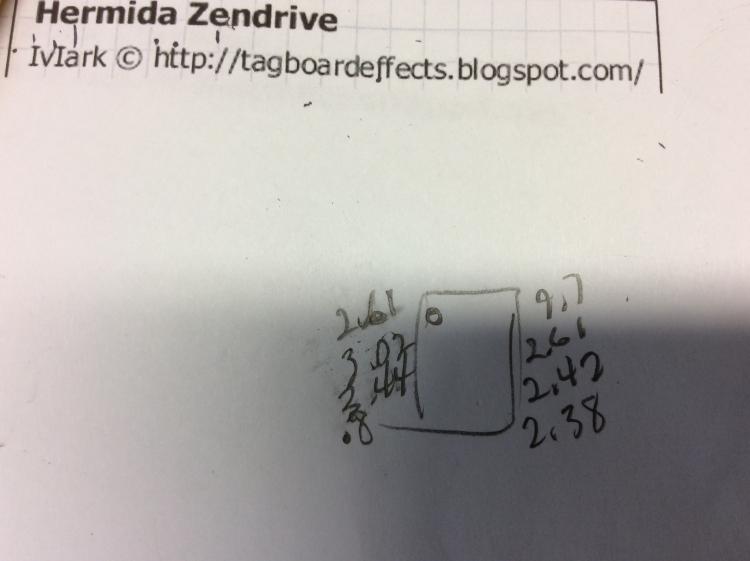
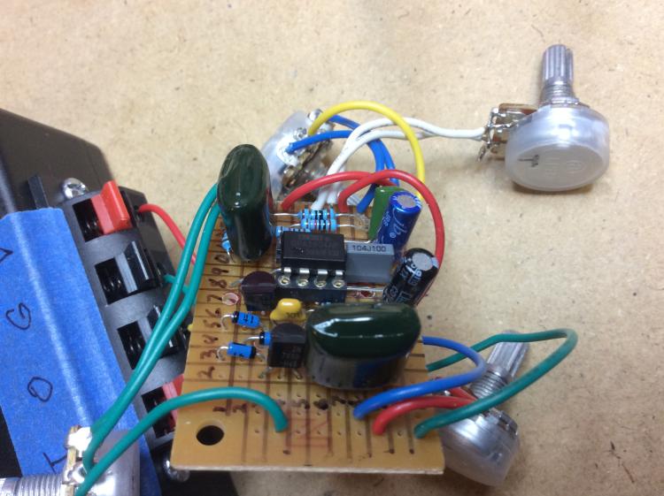
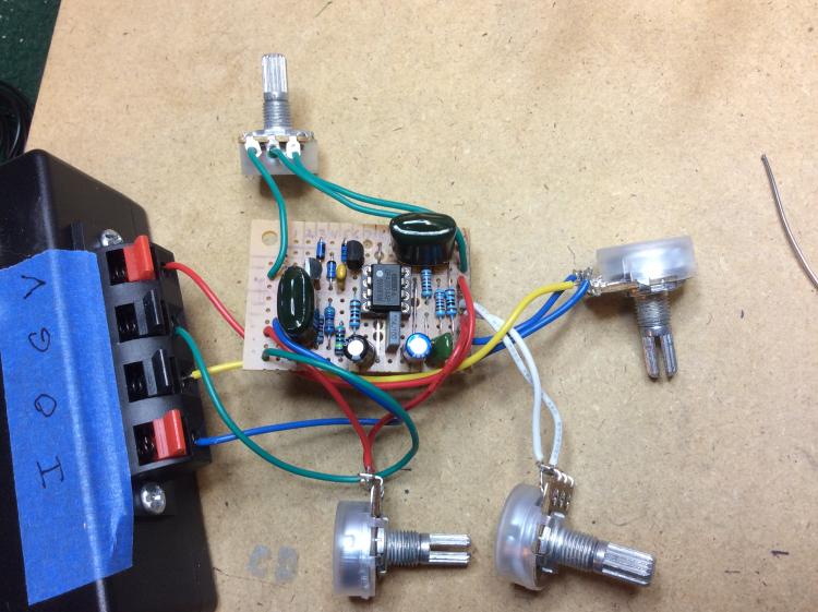
I tested each resistor and capacitor on DMM and capacitor tester respectively before soldering in. I did not socket my transistors or diodes on this build but tried to exercise extreme caution with solder iron heat when installing. After completing the board, I wired up my box and tested the off board wiring...signal passed...all good. I installed my board and tested. I get no sound when effect is engaged and the opamp starts to get very hot to touch after a minute or two plugged in with my EHX 9v adapter I use to test pedals on my bench. I took the board out and put on my test box (Miro's test box v2 from this site). Same results. I scored all my traces with razor to makes sure I had not solder bridges. I went through the layout again twice over consecutive days. After some internet research, I thought this may be bad opamp so I replaced with another opa2804. I got same result. I tried a JRC4558. It seemed to take a bit longer to get extra hot but did eventually. Still no sound. I've been at this several days and thanks in advance for any suggestions or help. I'm posting pics of my board and my opamp pin out readings in next post. |
|
Here are pics...
|
|
Administrator
|
The first thing that is apparent to me is that the voltage on pin 4 is a problem. Pin 4 should be grounded and you should have 0V there. I'm going to take a look at the pics now
|
|
Administrator
|
It's hard to tell what's going on in the pics, but something looks amiss around the lower left side of the board. Double check those resistors and the 470n cap
|
|
In reply to this post by Madmac
Hey Madmac,
I had a comparable problem with an IC heating up a few weeks ago. Turned out the legs of the socket/Opamp were not soldered well to my board. It's hard to tell in your pic, but it does look like if not all the legs of the socket are not soldered. I could very well be wrong. |
|
In reply to this post by Travis
Thanks. I'll go back and inspect that part of the board this evening after work. I'll report back. If still no luck, I'll try to post some better pics.
|
|
In reply to this post by Marbles
Hey thanks Marbles. Makes sense. I'll go back and reflow the solder over the pins on socket. I'll report back this evening after work.
|
|
In reply to this post by Travis
Hey Travis...first of all thanks for taking a look. That .8 showing on pin 4 looked odd to me but was unsure if this was just DMM reading anomaly since it was so low. I haven't yet gotten into reading schematics so should I be looking at the jumper from row 7 to row 11 as the path to ground and potential problem (i.e. bad solder joint) or the path of the 10k resistor to 47uf electrolytic or both? Not sure why my pics look cut in half on my work pc...they look fine on my ipad at home. |
|
In reply to this post by Travis
Hey Travis...I looked over that lower left side against the layout and things look ok. Here is close up...that 470n is huge and obstructs some of the board... 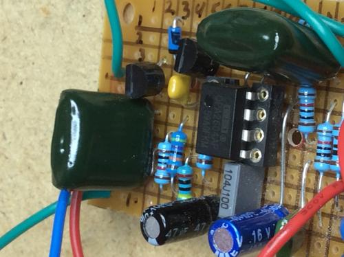
|
|
Administrator
|
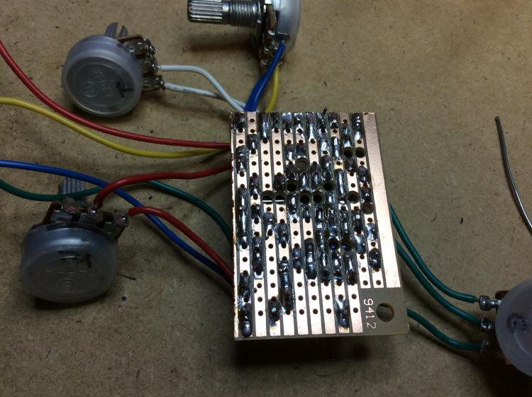
I just noticed that pin 4 does not appear to be soldered to the board. I can see that the link is soldered, and then I can see pin 4 of the socket seemingly not soldered
|
|
In reply to this post by Marbles
I took out the opamp and re-flowed the solder over the socket connectors. I also re-flowed solder over any suspect areas leading to ground. I tried a another chip (TL072). Hooked her up and tried it out but still no sound this time when I touched the chip (on less than 30 seconds) it was super hot. Like touching my soldering iron. I took the opamp out and tested pin 4 and I now am getting a 0 reading on the DMM so must be reaching ground. Getting 9.72 at pin 8. It's a fairly simple layout so I'm baffled. I'll post a couple of more pics if anyone can take a look. I appreciate any advice and your time looking at this. If all else fails, I'll try rebuilding the board. Got to get this one working cause I think I did a decent job on my box except got crooked on my Zendrive label....
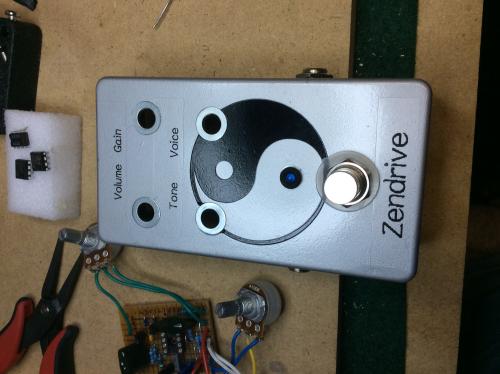
|
|
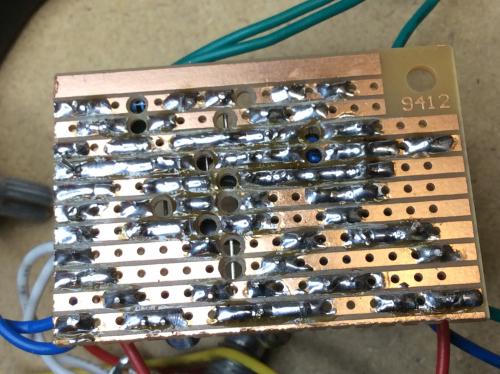
Here's some pics with opamp out...
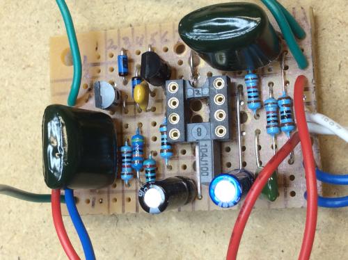 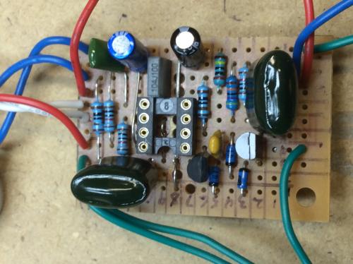 
|
|
Administrator
|
In reply to this post by Madmac
This is gonna sound redundant, but are you 100% sure pin 4 is soldered in and not contacting any of the surrounding rails? It doesn't look good in the pic.
Pin 8 is directly connected to 9V, so you will get whatever voltage reading your supply is putting out on that pin |
|
Administrator
|
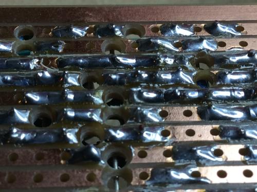
You can check continuity from pin 4 to ground to see if they are connected. If you get 0V with no IC, that doesn't really help you since you'd get 0V if it wasn't connected to anything at all
|
|
Travis, thanks again for looking at this and I don't mind redundant checks at all. I just used DMM to test continuity on pin 4 to ground and it's ok. Here's back of board pic closeup with pin 4 marked red...
|
|
Alright, I put the 4558 chip back in and it seems to not be heating up. Scary thought since I don't think I did anything different. A lesson on taking notes and test after every change. I still don't have output but I can start using probe. I need to learn how to use probe better...I end up getting a bit random when I lose following circuit. I'm getting output from pin 8 on Opamp...that must be good sign since that is output...right?
|
|
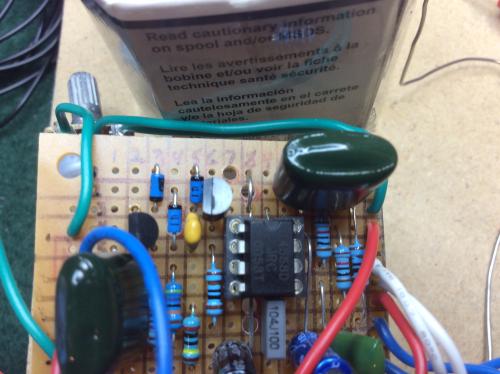
It's obvious I had a couple of issues going on but the opamp issue seems resolved thanks to Travis and Marbles!!! I haven't put the OPA2604 back in yet but I think it should be ok since the 4558 isn't misbehaving. I probed around from output backwards and got to the 470n cap on row 2...no sound but getting sound out of pin 6 and 7 of opamp. I'm wandering what should be carrying signal to that 470n on row 2...well according to diagram that should be the jumper on column 9. But lo and behold my jumper only goes to row 3! What a dumbass mistake. Between this and wiring up strats/Teles, you can really feel stupid with the mistakes you make but when you find them and fix them it's a great feeling. No time to fix tonight but hopefully tomorrow night I'll get to fix it, box it and test with my rig. Thanks a ton for the time you took to help me out! Here's a pic of the mistake so you can have a laugh...look at jumper on column 9.
|
|
In reply to this post by Madmac
I've been in your boat, and yes it's frustrating when everything seems OK but the effect doesn't work. I think your earlier experience with the chip heating up was due to the lack of ground at pin 4.
Here are some things to check: (1) Make sure there is NO continuity across the track cuts. I had a problem once that was the result of a tiny sliver of copper that I could barely see causing a bridge in a track cut. (2) Check the links, especially the double links, for continuity. (3) Your DC voltages on pins 1 - 3 of the IC should all be around 4.5 V. This is from the bias voltage produced by the 10K resistor voltage divider. In fact the entire second track from the bottom should be at 4.5 V. (4) Make an audio probe (if you haven't already) so you can find out where the signal drops out. Your output should be coming from pin 7 and not 8. Good luck!  Edit: Seems you've found the problem - good job! 
|
|
Administrator
|
In reply to this post by Madmac
Nice work Mac! Glad you were able to figure this out
Debugging is always a pain in the ass, but the fact that you worked through it will help you in the future. |
|
In reply to this post by Frank_NH
Thank you Frank! Some good advice. I am hoping that that re-flowing the solder over the opamp socket pins solved the overheating issue...not wanting my pedal board to go up in flames down the road.
 The voltages are very close with your #3 so I feel good about that. I learn a little more about electronics every time someone explains "why" the reading should be as they are like you did here which is a big help. And +1 on the probe. I do have one built in to my test box and used it to trace down that last problem with the jumper. Great tool. The voltages are very close with your #3 so I feel good about that. I learn a little more about electronics every time someone explains "why" the reading should be as they are like you did here which is a big help. And +1 on the probe. I do have one built in to my test box and used it to trace down that last problem with the jumper. Great tool.
|
«
Return to Debugging
|
1 view|%1 views
| Free forum by Nabble | Edit this page |

