layout help please, i'm at my wits end!
|
so i made this deluxe pitch pirate vero:
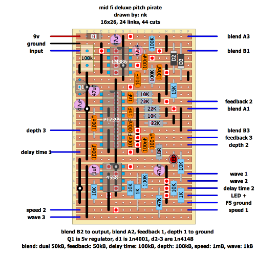
image: http://i.imgur.com/VFKgAEB.png  from this schematic: http://i.imgur.com/BEghkEo.png the LEDs all work, everything is peachy on that end, except i get no effect. when the blend knob is down, i get dry signal, but it just gets quieter as i turn the blend knob up, until there is nothing. problem: the 78L05 regulator gets REALLY hot. as in, it burned me. that hot. does anyone know what could be causing this? and i'm sure this would have something to do with why it's not working. i checked the schematic against my layout 100 times. what could i be missing? |
|
Your layout is small, i don´t understand too much but you connected ground to lm386 pin 4 instead -9v?
i think you must add a charge pump with both positive and negative (9v) ... and ground must be neutral. |
|
In reply to this post by adapt
First things first: your 78L05 is reversed in your layout. If it's installed that way, it can kill the regulator and would account for the overheating and lack of delayed signal. It also may have fried your PT2399.
If you actually installed it the right way, read on. Some PT2399's are prone to lockup. When this happens, there will be no delayed signal, and the regulator will get hot. If the condition persists long enough, it can burn out the PT2399, so pull the power as quickly as possible if it doesn't fire up correctly. Many have claimed that once the chip locks up once, it will continue to lock up forever. That hasn't been my experience (see below). Even after overheating, I've never had a regulator fail this way (assuming it's oriented correctly), but YMMV. I haven't looked closely at your layout, so don't discount the possibility of an error, but this behavior is very common in PT2399 circuits even when the layouts are correct and the circuit is built correctly. I have seen several recipes for avoiding lockup on DIYSB and FSB, so you can do some research with the search function ("PT2399 lockup") on those sites. That said, the thing that has worked for me was to knock down the voltage supply to the PT2399. I think sometimes these chips are sensitive to too much voltage (others may have different experiences), and that 5V is too much for some of them. In all of my builds, I put an Si diode (1N4001, etc.) between the regulator output and the voltage supply pin on the PT2399. This knocks the voltage supply down to just under 4.5V, and invariably avoids the lockup problem, even on chips that have locked up in the past (as long as the power was pulled quickly enough and the chip didn't die). I bought my PT2399's from China ridiculously cheap ($0.50 each). Many claim that the cheaper ones are either defective, counterfeit, or picked through. I tested every one of mine and many of them locked up when fed a 5V supply, but every single one worked flawlessly with the diode trick. It's worth a try at least. |
|
In reply to this post by boratto
I think it is meant to be ground.
There is a verified layout in Contributions. Looking at your layout the 78L05 should be inverted 180 degrees. |
|
This post was updated on .
ho-hum, nothing to see here
|
|
ok, so now here's the problem...
so i get no effect, EXCEPT for when i turn the delay time knob ALL the way up. it's not so much an effect as it is a blast of noise, but all the controls modify it. the wave, depth and all that make it sound different, and if i turn feedback up, the white noise grows louder and louder, like oscillation. something is garbling this, does anyone see any errors in the layout? edit: full disclosure, the trimpot is one of those multi-turn types. i hope that doesnt make a difference. if i turn it in one direction really fast for a minute or so, the signal farts out completely. other than that, it doesnt seem to do much. |
|
got it working!!!! yesss!!!! thanks for all the help guys!!!!
|
|
What was the problem?
|
|
one of the track cuts under the 2399 had a microscopic piece of copper connecting the two sides
|
|
Good spot. I've had this happen before too. Now I always use my DMM to run a continuity check (or should I say a lack of continuity check), after doing all my cuts, before going on to build up the board.
I also give it a good look over with a magnifying glass in case I have a sliver of copper remaining, that might fold back over and short out - that's happened to me too! 
|
|
it's one of those things that you have to add onto your list of stuff to do every time just because it's happened once. been building pedals for like 7 years now and i'm still refining the process!
|
«
Return to Open Chat
|
1 view|%1 views
| Free forum by Nabble | Edit this page |

