lunar collision
|
It is a very low parts wah-tremolo, I like the sounds a lot,
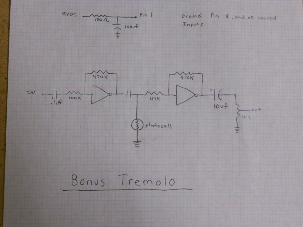
http://www.youtube.com/watch?v=_CVqZBxxO4k   there's a tremolo part too, not as impressive as other tremolos at the blog, but here it is. Thank you! Sergio |
|
Wow, that sounds great!
|
|
This post was updated on .
In reply to this post by Sergio
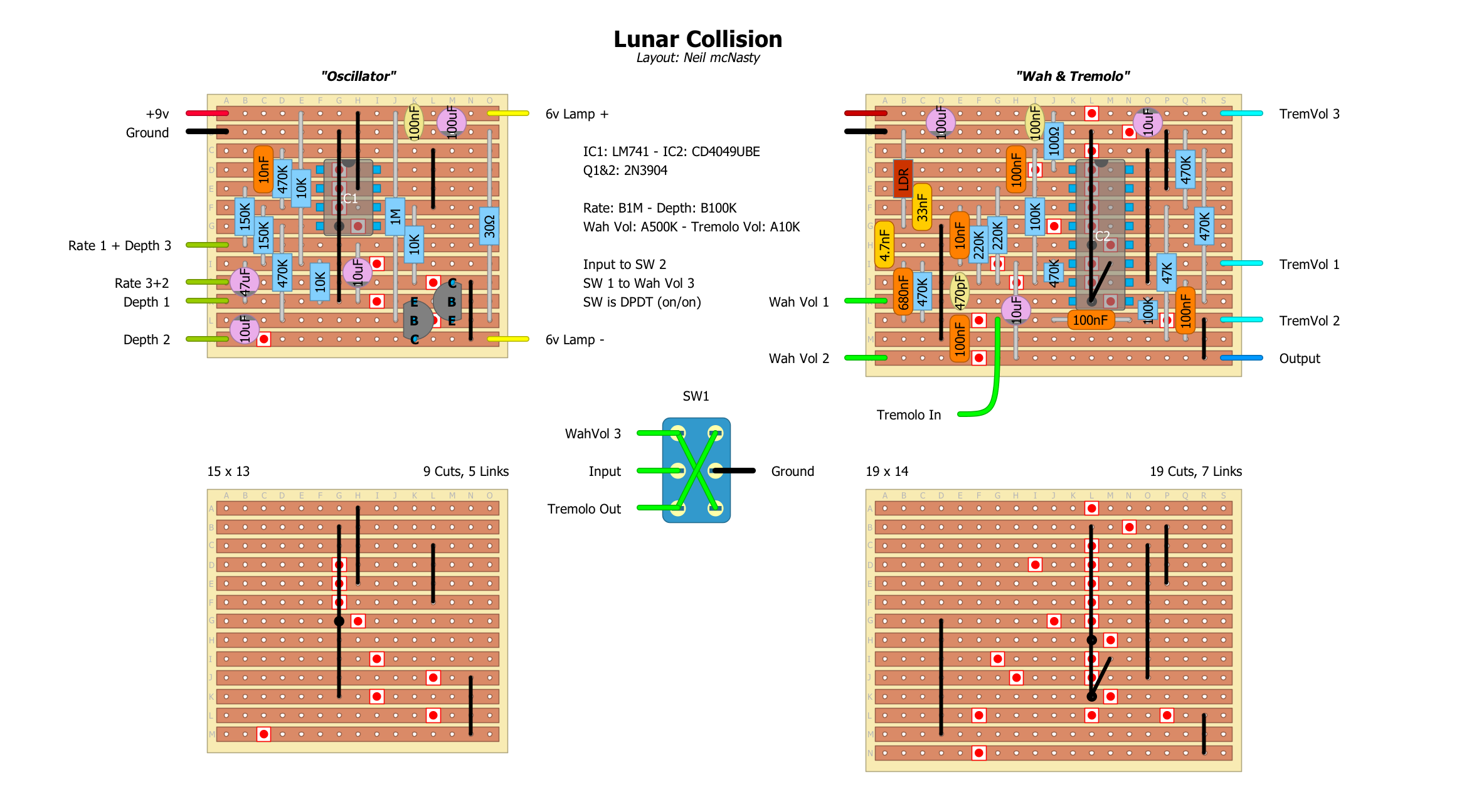
I'm drawing up this one at the moment, but there is too much information missing in order to get a proper layout done:
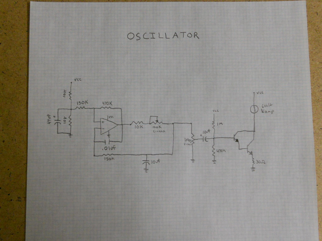
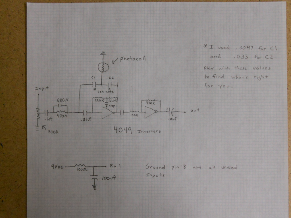
- What is the IC for the Oscillator? - What are the transistors? - What is the value of the two caps that are not marked? - What are the pot functions? - Are all variable resistors (pots) normal pots or are any of them trim-pots? Does anyone have any information on this? My idea is to build it with the Tremolo as well, and add a switch that selects between Wah and Tremolo... |
|
Yes, it really sounds wonderful.
I myself would prefer LED's instead of an incandescent lamp. An LED will live longer When the alterations of the light are too fast a lamp will no be able to follow because the of the time it needs to heat up and cool down. I built a compressor that way and during the attack it produced a huge peak due to the lag of the lamp. |
|
To Neal, to answer you questions
- What is the IC for the Oscillator? For the oscillator you can use the simplest opamp, even a 741 - What are the transistors? any transistor able to dissipate 1/2 Watt is usable - What is the value of the two caps that are not marked? See the remarks written with the *'s - What are the pot functions? Page 1, Left Speed, Right depth Page 2, Input Gain - Are all variable resistors (pots) normal pots or are any of them trim-pots? All normal pots |
|
In reply to this post by bassbuddy
I agree it sounds great. I also agree that led's are much simpler and last much longer, but I fear that using led's instead of the lamp may change the sound. I could be wrong, but every led-based Univibe-type circuit that I've heard has sounded much different to me than the ones with the incandescent lamps. I believe that the inherent lag smooths out the light-dark transition in a nice way. The led's respond more quickly, and thus less smoothly. Certainly worth a try, though. Spikes aren't a problem with vibe circuits the way they are for compressors because their timing is entirely controlled by the LFO, not by the input signal. |
|
In reply to this post by Sergio
Iasked in the comments of the video for the details that seemed to be missing, that was the answer, nice indeed. Hope it helps.
Sergio Thanks for the kind words. The IC for the oscillator is LM741, the transistors are 2n3904, the two caps with the asterisk are for (C1=.0047, C2=.033). The unlabeled coupling cap between stages is .1uf . The 100k pot is speed, the 1 Meg is the depth. No trimmers were used. If you have anymore questions I can also be found on freestompboxes, and diystompboxes as lapsteelman. Thanks for your interest |
|
I understand your concerns. I did not realize that the wien-bridge oscillator supplies a "sine"wave and that too fast light alterations are no issue. That also goes for lifecycle concerns. Since that compressor I kind of abandoned the idea of using lamps. But I still have some so-called raysistors lying around. They are a small  and a LDR combined in a transistor housing. In a dim past they were used as opto couplers a la lettre. Now they come in the frame for future projects. and a LDR combined in a transistor housing. In a dim past they were used as opto couplers a la lettre. Now they come in the frame for future projects.
The warming-up and cooling-down characteristics of an incandescent lamp could be simulated with LED's but make things needlessly complex in this case. But where lifecycle of lamps is an issue it is a possibility.
Have a nice day, friendly greetings. 2014-07-09 10:19 GMT+02:00 Sergio [via Guitar FX Layouts] <[hidden email]>: Iasked in the comments of the video for the details that seemed to be missing, that was the answer, nice indeed. Hope it helps. P Please do not print this email unless it is absolutely necessary. Spread environmental awareness.
|
|
In reply to this post by Sergio
I have not built and verified it yet, but I will build this some time next week...
Sorry about not being able to make the layout neat and compact, but I'll try to do another one at a later point, in hope of getting it smaller. I've added the Tremolo as well, so you can switch between Wah & Tremolo on the switch. If you are very experimental, it could be an idea to try to replace the switch with a pot, so that you can run both effects at the same time and adjust the balance between them. (I will certainly try that...) Enjoy! 
|
|
Anyone ever give this a build?
|
|
In reply to this post by Sergio
Hallo, I was having a look at this before trying it, and Could it be theres something wrong around the oscillator part? I think parts around pins 2,3,6 are a little mixed, or at least I think so looking at schematic.
Because pins 2 and 3 are not meeting at point 6 , am i right? I have not used a vero designing program before. But I think a little fixing needs to be done. Thanks anyway, a good starting point! Sergio |
|
Looks fine to me...
pin 2 connects to pin 6 via 10nf cap, and pin 3 connects to pin 6 via 470k resistor just like the schematic. Been very busy touring almost nonstop since end of March, so I have not been able to build this one yet, but it's at the very top of my list, as soon as I get back to my cave. Hopefully next week... |
|
I have now tried to build this, but seem to have some problem getting the LFO going.
It flashes one time when powering up, and then it seems like it can not produce enough energy to keep it going. Sometimes it flashes one more time if I turn the speed and depth up and down a bit. Unfortunately I do not have the circuit where I am now, but I'll be continuing doodling with it as soon as I'm back in my cave in Oslo, a week or two from now... Neil |
«
Return to Requests
|
1 view|%1 views
| Free forum by Nabble | Edit this page |


