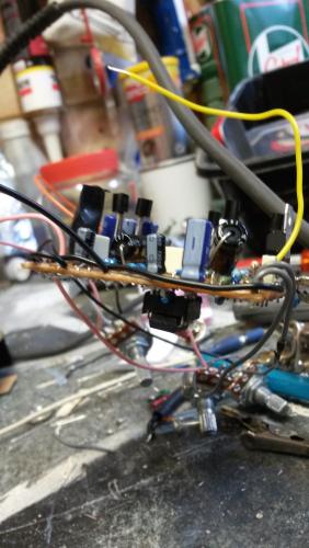
reversed vero issue

classic Classic list List threaded Threaded
7 messages Options
Reply | Threaded
Open this post in threaded view
|

reversed vero issue

Ubertech_s
Hi All

I am currently building the Forest Green compressor as my first vero build. I have built several other boards up from PCBs.

I made an error right at the beginning, I didnt realise the vero cuts and links diagram needs reversing - ouch! Regardless (because I had already started) I have tried to build up the board in flipped horizontal, and I think it is gtg, but it doesnt work obvs.

I just wanted an opinion - if I have built it in flipped horizontal everything on my build will be reversed except the chip pin layout?? The chip does get a little hot lol.

So by flipping the pins 1-8, 2-7, 3-6 and 4-5 by soldering some jumpers, or even by soldering the chip to the bottom of the board I could get rid of the inbuilt error

What do you think?

btw I know the error of my ways and wont do this again ;)
Reply | Threaded
Open this post in threaded view
|

Re: reversed vero issue

ξεναγος νεκροπολης
i would say to start over again. if the layout had a few transistor it might be worth trying to reverse pins and staff. but now...no...
start a new board.
and the chip is 99% dead now...
sorry mate..
it's a common mistake that people do when they first start on vero.
there is a step by step guide on the main site that will help you a lot.
http://tagboardeffects.blogspot.gr/2012/04/vero-build-guide.html
Reply | Threaded
Open this post in threaded view
|

Re: reversed vero issue

induction
Reversing the component placement left to right should work, if there are no other errors. You could solder the IC on the back of the vero, but that should be the only modification to the reversed layout. The transistors and the voltage regulator don't need to be flipped.

If you put the IC in backwards and it got hot, it's probably dead. Try replacing it (oriented correctly). If it still doesn't work, there's another problem to be found. You could start from scratch, or you could post photos of your build and I bet we could get it working. Your choice.
Reply | Threaded
Open this post in threaded view
|

Re: reversed vero issue

Ubertech_s
In reply to this post by Ubertech_s
it lives!!


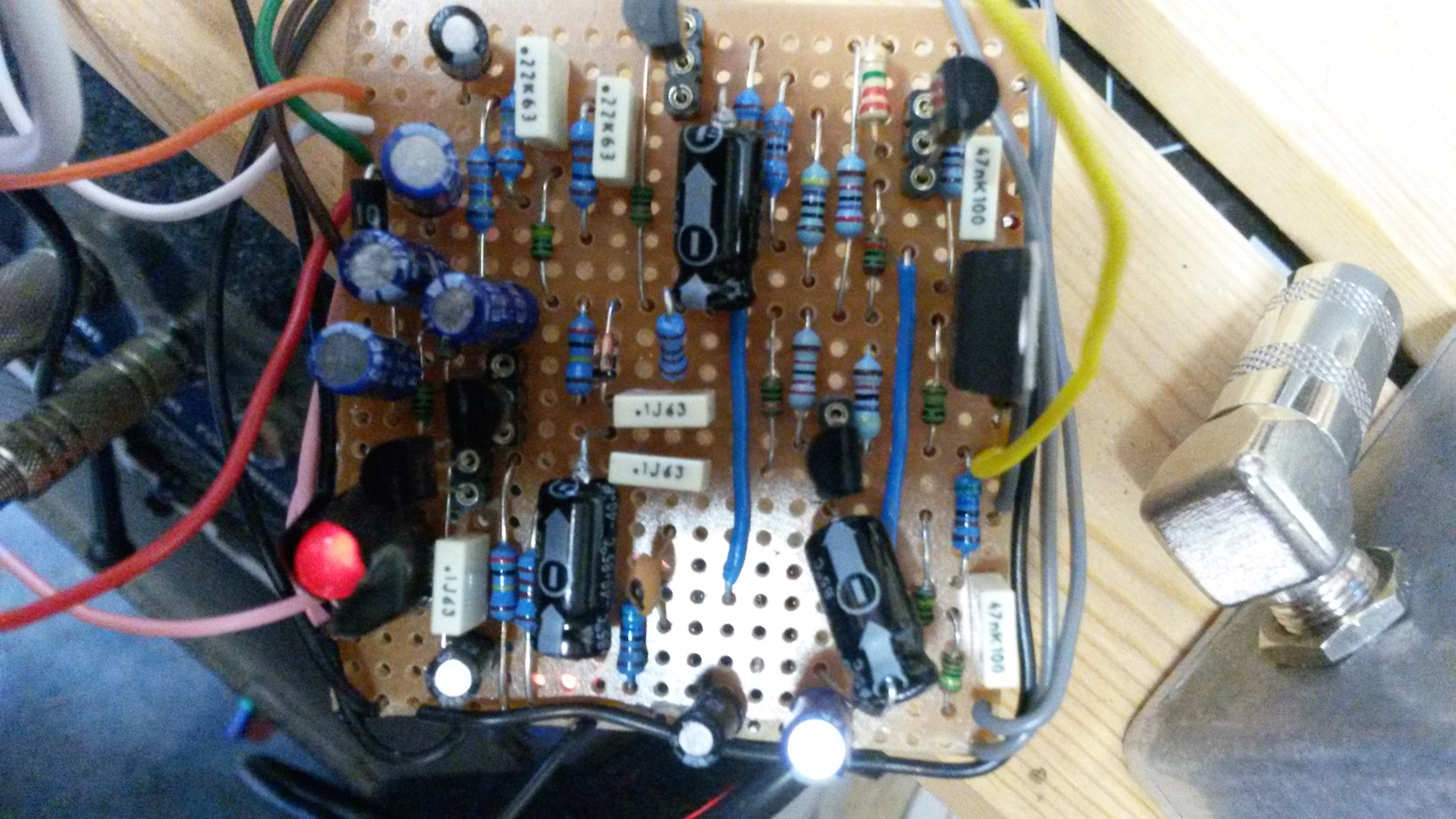
the LED lights up as it should see photo, Ive black taped it here to the LDR just to test it

I desoldered the 8 pin socket and slung it underneath the board, so that it was the same way up/down, but reversed left/right


the chip actually survived its reverse wiring!

The build is super-clean sonically, and optical compression is so suited to guitar transients - as it is naturally slow acting compressor the transients are left untouched so you dont get that squashed sound, just a load more weight and eveness to the dynamics

Result!
Reply | Threaded
Open this post in threaded view
|

Re: reversed vero issue

induction
Good job. Glad you got it sorted.
Reply | Threaded
Open this post in threaded view
|

Re: reversed vero issue

Ciaran Haslett
In reply to this post by Ubertech_s
Great job!  I especially like the Irish Tricolour you have going on with the wiring

One thing I will mention...that regulator is massive (rated 1 amp?) and now with the IC on the other side, you might struggle to get it into a 1590B and close the lid.  If you do struggle, try a 125B.  Roughly the same size but deeper.

Congratulations.
Reply | Threaded
Open this post in threaded view
|

Re: reversed vero issue

Ubertech_s
thanks for the tip

I was worried about the regulator when my supplier sent it - I was expecting it to be tranny sized. The pins were so thick I couldn't socket it.

I think I may source a smaller one and swap it out. Thanks for the enclosure idea - Im going to mount it in series with the output into a Mad Bean Slambox (simple boost) so I may need the extra room anyway and I dont want to go BB size

Compression into boost, both with their own level controls and on/off switches; a nice 125B utility

Thanks for all the help

UT