simple mod to switch between LDR and Potis
|
Hey
So I've been thinking how cool it could be if to effects like tremolo the SPEED pot could be switched to be controlled with a photo cell resistor so the speed could be slower / faster within the waving of a hand or the preventing / allowing light exposure with the foot to a photo cell resistor. Same goes for the TIME function of any delay. Currently I got plany SPDT switches. Can I use them for this type of mod ? if so, then how ? thank's in advance! Assaf |
Re: simple mod to switch between LDR and Potis
|
This would be awesome for selecting between pots and vactrols as well.
|
|
Im sure its an easy thing... will someone be kind to hand in some related read on moding with switches and so on ?
would be a 100000000000x thank you from my side ! ! ! |
Re: simple mod to switch between LDR and Potis
|
that is what your post reminded me...
tones of madness that's what i want to be when i grow old... http://guitar-fx-layouts.42897.x6.nabble.com/Peter-Vogel-The-Sound-of-Shadows-tp14023.html and a direct link https://vimeo.com/59829961 |
Re: simple mod to switch between LDR and Potis
|
This post was updated on .
In reply to this post by Tune Tone
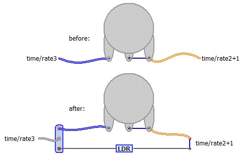
Both tremolo rate and delay time controls are usually simple rheostat/variable resistance controls: they can easily be replaced by an LDR. Disconnect one "end" of the existing control and solder it to one of the outer lugs of the SPDT, solder one end of the LDR to the other outer lug, solder the other end of the LDR to the still connected end of the pot, and connect the middle common lug of the switch to the original point you first disconnected the pot from <edit/ i did a picture>
 It's worth measuring the fully dark maximum resistance of the LDR, it is likely to be higher than the maximum resistance of the original pot. In this case, wire a resistor of a lower value in parallel with the LDR to set the maximum resistance (I.e. for when the LDR is completely blocked). For example, a pt2399 increases delay time as the pin6 to ground resistance increases. Above 100k, it starts to get extremely graunchy and low fi due to sample rate reduction as the delay time goes up above a whole second. If you have a 1M dark LDR, you would probably want to parallel.it with a 100k fixed resistor to set the maximum to approx 100k. |
|
thanks a lot, so in general I think I got it. I got LDR is different values. Its all becasue I experienced with the Clari (not) and bought LDR in different dark/bright values. Now I want to do something cool with the rest that I got and also I always wanted to blend LDR in pedals I build to give in the effect of Theremin and people could act stupid in front of the toys I build for them
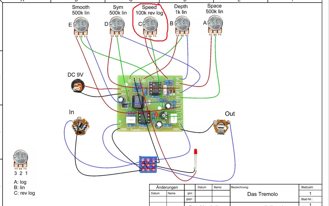
 One thing thoug... now Im looking ath the tremolo I built lately from teh MusikDing.de kit. Speed pot lugs 3 and 2 are soldered while 1 remains free.. so I guess the rheostat is being done within the PCB, right ? in this case I can treat Lug 2 as the orange wire in the wiring plan you posted ?? thanks a bunch 
|
|
strangly enough.. I think all my LDR do not go over 80k when dark. Or could be Im missing something in the measuring process ?
I measure once with my finger blocking the surface of the LDR and once without blocking revealed to the windows (theres day light). when blocked te resistence is getting bigger and when reaviling it to light its going down. Its strange cause my supplier states on the plastic bags 36k - 500k - where this LDR measures 5 - 6 K when blocked and 0 when non blocked. as for another one: which states 10k - 25k on the bag - I measure with 3 - 4 when exposed and 40 - 50 k when blocked. |
Re: simple mod to switch between LDR and Potis
|
In reply to this post by Tune Tone
For rheostat arrangement, you only need to use two lugs but many schematics and pedals have the unused luge tied to the wiper. This means the pot doesn't go open if the wiper fails and breaks contact with the track, and instead the pot will default to it's maximum setting: so e.g. a PT2399 delay would have a "broken" time pot but was restricted to only the maximum delay setting instead of infinity-resistance glitchy bit-crushed nonsense sounds. For the trem you have shown, you could snip the wire from lug 2 and treat it exactly as the linked lug2+1 connection on my diagram (effectively exactly the same thing).
As for the values, it seems LDR true values are rarely what the manufacturer or vendor says they are (i think their manufacture is an inexact science), but also you don't always know what conditions they were notionally tested under: It is very hard to test them at home to total darkness unless you actually completely envelope them in light-proof material (i.e. they seem to be able to detect light from the underside). It's always worth buying a few different values of LDR (e.g. 10-200k, 20-500k, 10k - 1M etc) to try out for this type of modification. |
|
ok so everything seems to work now. I used a DPDT in the end to add an LED indication when the mod is on or off.
So now the LDR is still free in no some kindof a casing. so once its blocked the speed is low and when its exposed the speed is higher but still not high as the speed poti is able to give, what shall I try now in this case ? I used an LDR which is stated as 36k - 500K and they are also quiet big to slide in a 5mm LED bezel. What other type of casing I can try ? eventually I want it to be fixed on the box of course. Or shall I first try the oder LDR I got cause they could fit a 5mm LED bezel. cheers and thnkas a lot! |
Re: simple mod to switch between LDR and Potis
|
Try wrapping the LDR in heat shrink until it's thick enough to catch in a 5mm bezel
|
Re: simple mod to switch between LDR and Potis
|
In reply to this post by Tune Tone
The fastest available when using the LDR will depend on both the minimum resistance of the LDR when illuminated, and the amount of ambient light that falls on the LDR when totally exposed. This second part is the main drawback of using an LDR as a control: If you turn the room lights out, the maximum speed drops dramatically. You could put a scaling resistor in parallel with the LDR but this will increase the slowest rate available as well as the fastest rate possible.
|
«
Return to Open Chat
|
1 view|%1 views
| Free forum by Nabble | Edit this page |

