Hi,
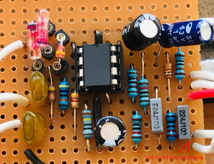
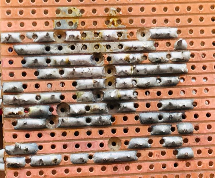
I built a Son of Screamer on vero (see images below), but it isn't working.
Please help. This circuit has kicked my butt for several days now. For some reason I refuse to throw this thing into my box of broken circuits. It's become personal... I can't think of anything else. I've stopped shaving and brushing my teeth, and am considering quitting my job so I can work on fixing this thing full time.
4558 chip voltages:
1: 1.5
2: 1.1
3: 1
4: 0
5: 8.7
6: 2.2
7: 2.2
8: 2.2
Note: voltages at pins 1, 2, 3, 7, 8 and 9 fluctuate ~.3v either way. I couldn't get a steady reading, the voltages went up a little then down and back up.
Sound check (via audio probe):
If I bypass the circuit, then I get clean guitar sound.
When touch the probe to the input lead on the board before it even gets to the 47n cap, I can hear the signal, but it's like there's a wind blowing in the background.
At pin 3 of the chip, I still get fairly clean signal but a little more "wind".
At pin 1 (output A) of the chip, even more wind, but I can still hear the guitar signal. I can hear notes, chords, etc.
At pin 7 (output B), I can't hear any guitar signal, just a whirlwind of static.
What I've done to check things, so far...
I made sure all cuts, links, and components were in the correct position.
I swapped out the chip for another 4558. (no change)
I checked for solder bridges, etc. with a multimeter
I was using a ceramic 49p cap and i ripped it out thinking it may be causing some noise. but it still sounded bad without it. I'm assuming the circuit will work without that cap.
Schematics:
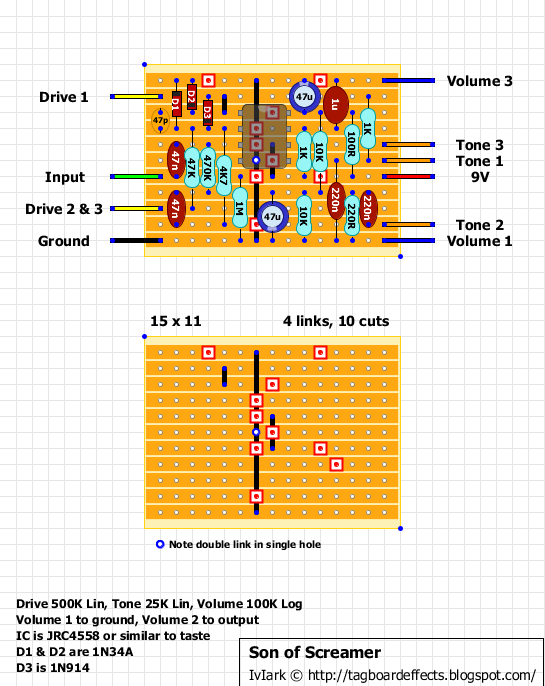 Vero pics
thanks for any hints or sage advice.

