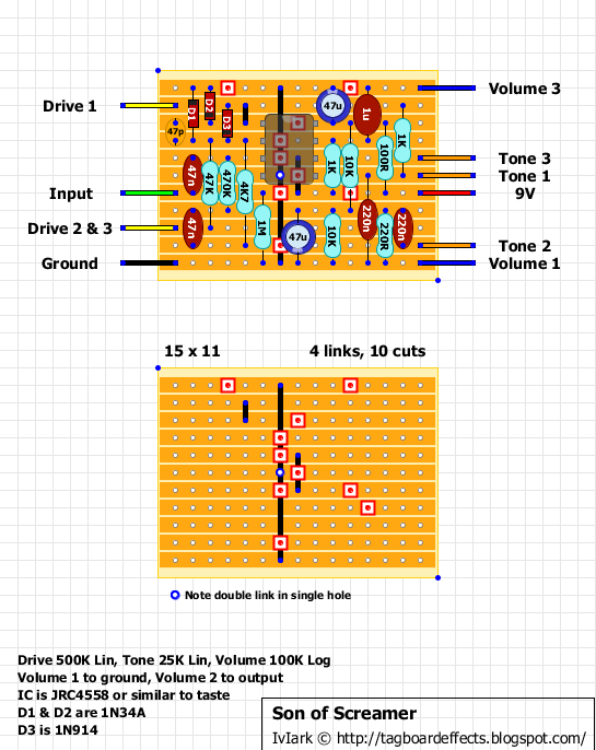
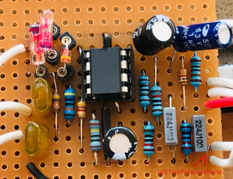
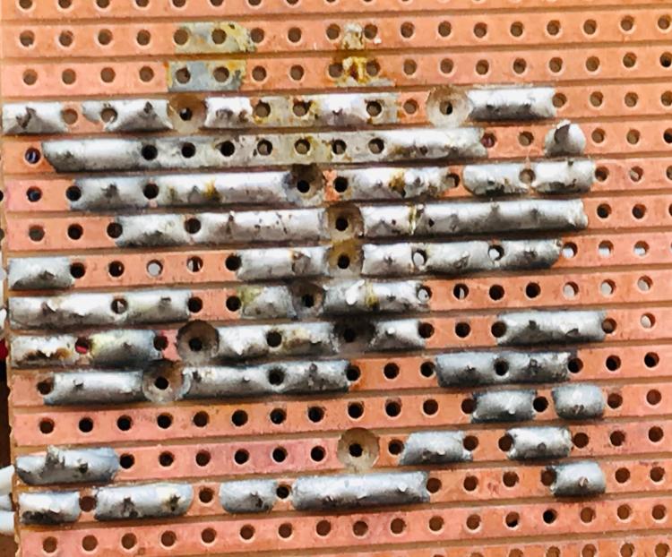
the son ain't screamin [fixed!]

classic Classic list List threaded Threaded
5 messages Options
Reply | Threaded
Open this post in threaded view
|

the son ain't screamin [fixed!]

joejoe
This post was updated on .
Hi,

I built a Son of Screamer on vero (see images below), but it isn't working.

Please help. This circuit has kicked my butt for several days now. For some reason I refuse to throw this thing into my box of broken circuits. It's become personal... I can't think of anything else. I've stopped shaving and brushing my teeth, and am considering quitting my job so I can work on fixing this thing full time.

4558 chip voltages:

1: 1.5
2: 1.1
3: 1
4: 0
5: 8.7
6: 2.2
7: 2.2
8: 2.2

Note: voltages at pins 1, 2, 3, 7, 8 and 9 fluctuate ~.3v either way. I couldn't get a steady reading, the voltages went up a little then down and back up.

Sound check (via audio probe):

If I bypass the circuit, then I get clean guitar sound.

When touch the probe to the input lead on the board before it even gets to the 47n cap, I can hear the signal, but it's like there's a wind blowing in the background.

At pin 3 of the chip, I still get fairly clean signal but a little more "wind".

At pin 1 (output A) of the chip, even more wind, but I can still hear the guitar signal. I can hear notes, chords, etc.

At pin 7 (output B), I can't hear any guitar signal, just a whirlwind of static.


What I've done to check things, so far...

I made sure all cuts, links, and components were in the correct position.
I swapped out the chip for another 4558. (no change)
I checked for solder bridges, etc. with a multimeter
I was using a ceramic 49p cap and i ripped it out thinking it may be causing some noise.  but it still sounded bad without it. I'm assuming the circuit will work without that cap.


Schematics:
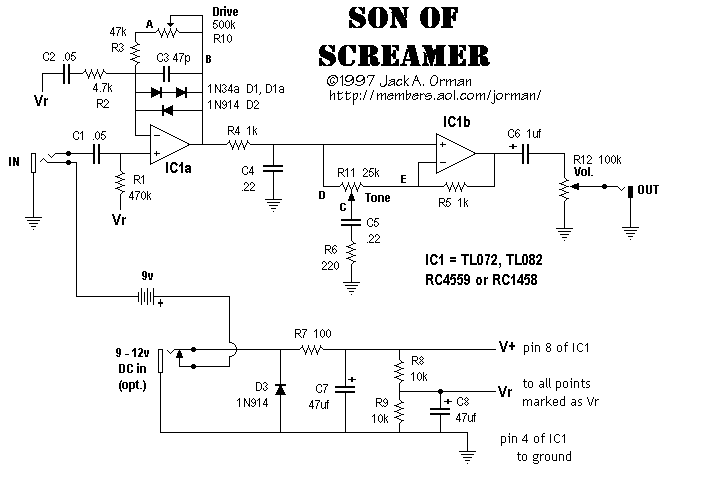


Vero pics


thanks for any hints or sage advice.
Reply | Threaded
Open this post in threaded view
|

Re: the son ain't screamin

Axldeziak
Looks like solder bridges between the 100r and the 220r, as well as the 1k and the 10k on the power rail. Knife between ALL the traces. And then go back and do it again. Use a magnifying glass or jeweler's loop to inspect them all under a bright light.
Reply | Threaded
Open this post in threaded view
|

Re: the son ain't screamin

alltrax74
In reply to this post by joejoe
Pin 8 should see V+
You should mesure them like this (maybe you inverted pins 5 and 8)
1     8
2     7
3     6
4     5

Also check that 4k7 resistor that should be connected to pin2, the lead seems to go under the IC
Your solders should look shiny, they all seem cold but that may be the pic


Reply | Threaded
Open this post in threaded view
|

Re: the son ain't screamin

joejoe
In reply to this post by Axldeziak
I cleaned up between the traces and it works!  thanks Axideziak!  I tested with the multimeter in continuity mode where I thougth there might have been a bridge and it didn't beep!  so I didn't think that was the issue.  but when I cleaned between the traces suddenly it worked.  
Reply | Threaded
Open this post in threaded view
|

Re: the son ain't screamin

joejoe
In reply to this post by alltrax74
thanks for the reply, Alltrax74. yep, i think i inverted the numbers.  the 4k7 is correct, just a bad camera angle. and yes, i think the soldering job i did sucked. they didn't look shiny like they should have.  actually i think my iron was too hot. the flux burned off too quickly.   I'm using a 30 watt iron and I noticed I did get nice, shiny solder contacts just after I turned the iron on before it heated up fully.