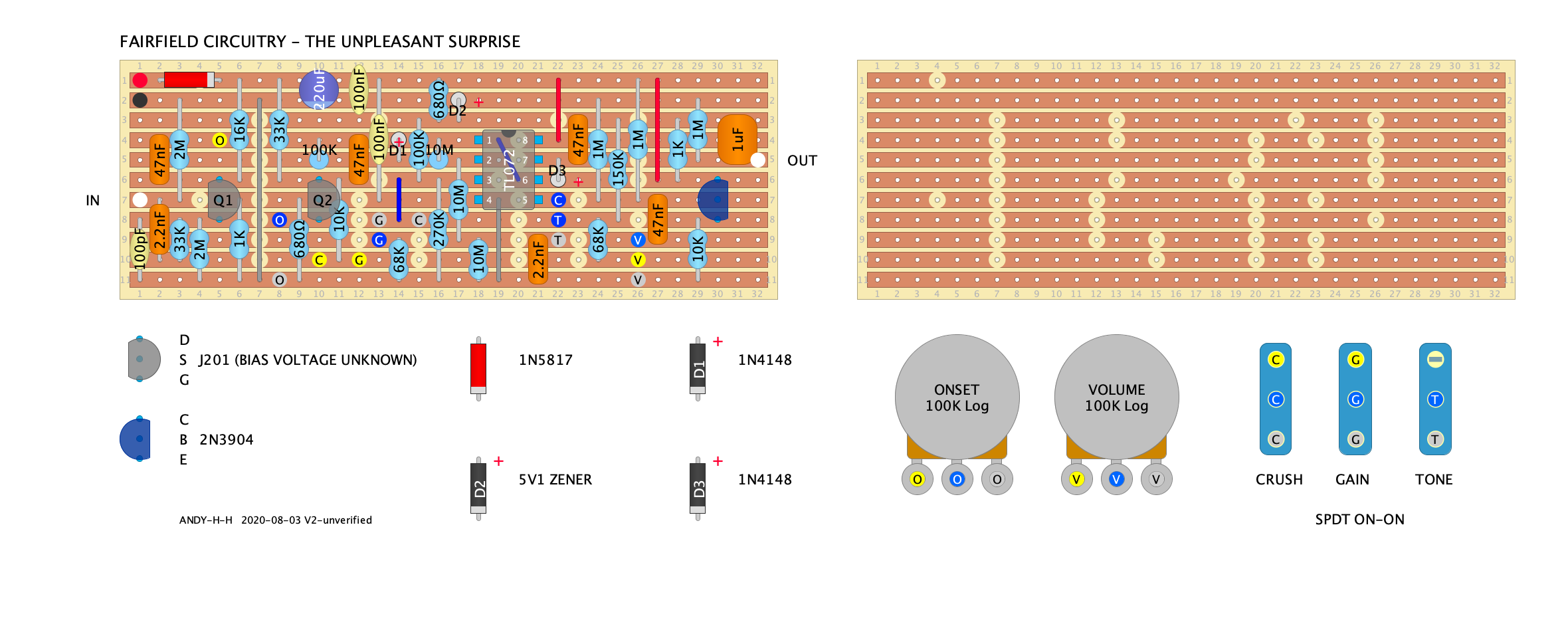
FAIRFIELD CIRCUITRY - The Unpleasant Surprise

123

123
FAIRFIELD CIRCUITRY - The Unpleasant Surprise

|

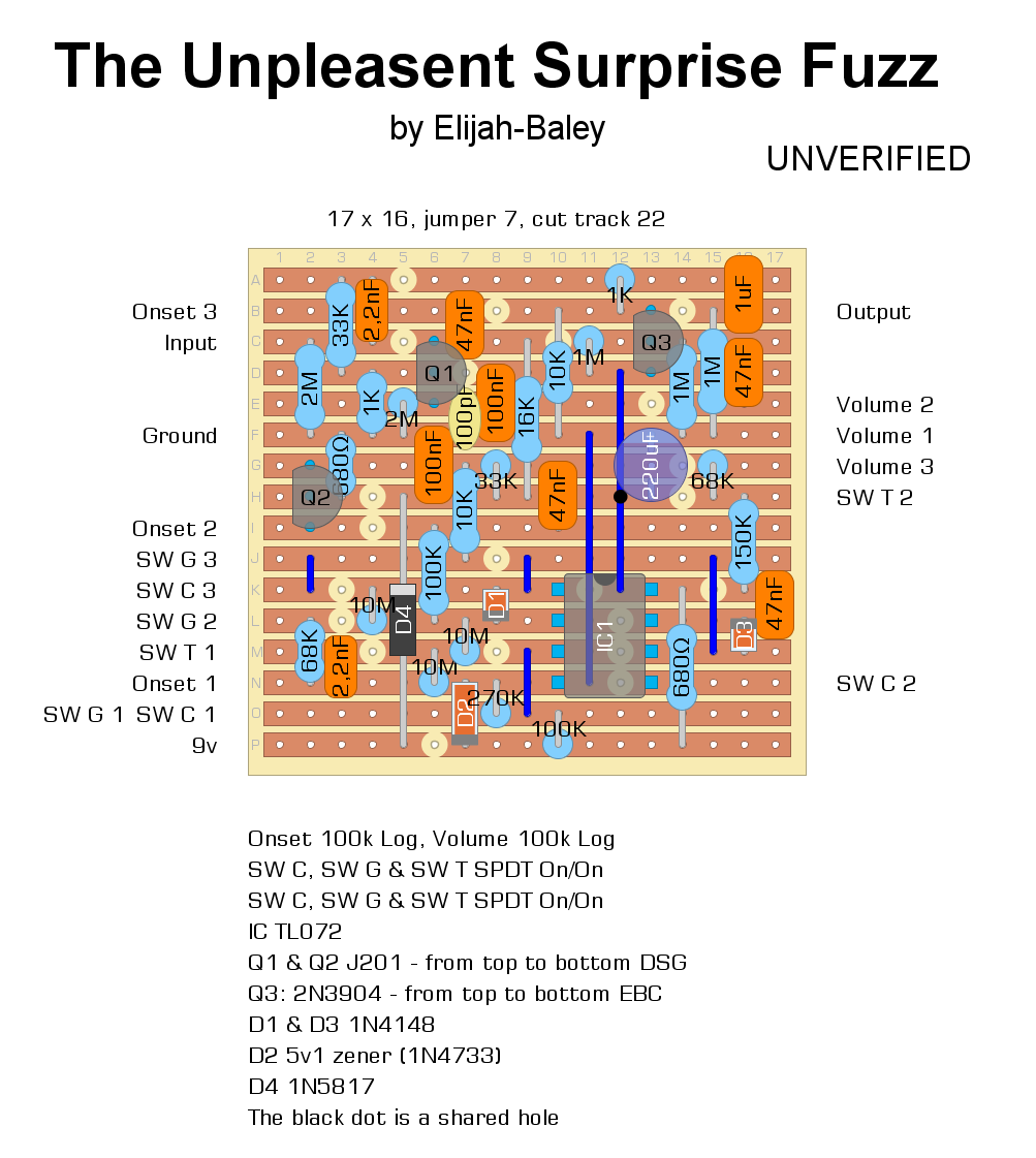
 PS the layout below looks better by the way.
Re: FAIRFIELD CIRCUITRY - The Unpleasant Surprise
|
|

Re: FAIRFIELD CIRCUITRY - The Unpleasant Surprise
|
|
Re: FAIRFIELD CIRCUITRY - The Unpleasant Surprise
|
|

Re: FAIRFIELD CIRCUITRY - The Unpleasant Surprise
|
|
Re: FAIRFIELD CIRCUITRY - The Unpleasant Surprise
|
|
Re: FAIRFIELD CIRCUITRY - The Unpleasant Surprise
|
|
Re: FAIRFIELD CIRCUITRY - The Unpleasant Surprise
|
|
Re: FAIRFIELD CIRCUITRY - The Unpleasant Surprise
|
|
Re: FAIRFIELD CIRCUITRY - The Unpleasant Surprise
|
|
Re: FAIRFIELD CIRCUITRY - The Unpleasant Surprise
|
|
Re: FAIRFIELD CIRCUITRY - The Unpleasant Surprise
|
|
Re: FAIRFIELD CIRCUITRY - The Unpleasant Surprise
|
|
Re: FAIRFIELD CIRCUITRY - The Unpleasant Surprise
|
|
Re: FAIRFIELD CIRCUITRY - The Unpleasant Surprise
|
|
Re: FAIRFIELD CIRCUITRY - The Unpleasant Surprise
|
|
Re: FAIRFIELD CIRCUITRY - The Unpleasant Surprise
|
|
Re: FAIRFIELD CIRCUITRY - The Unpleasant Surprise
|
|
Re: FAIRFIELD CIRCUITRY - The Unpleasant Surprise
|
|
Re: FAIRFIELD CIRCUITRY - The Unpleasant Surprise
|
|
| Free forum by Nabble | Edit this page |