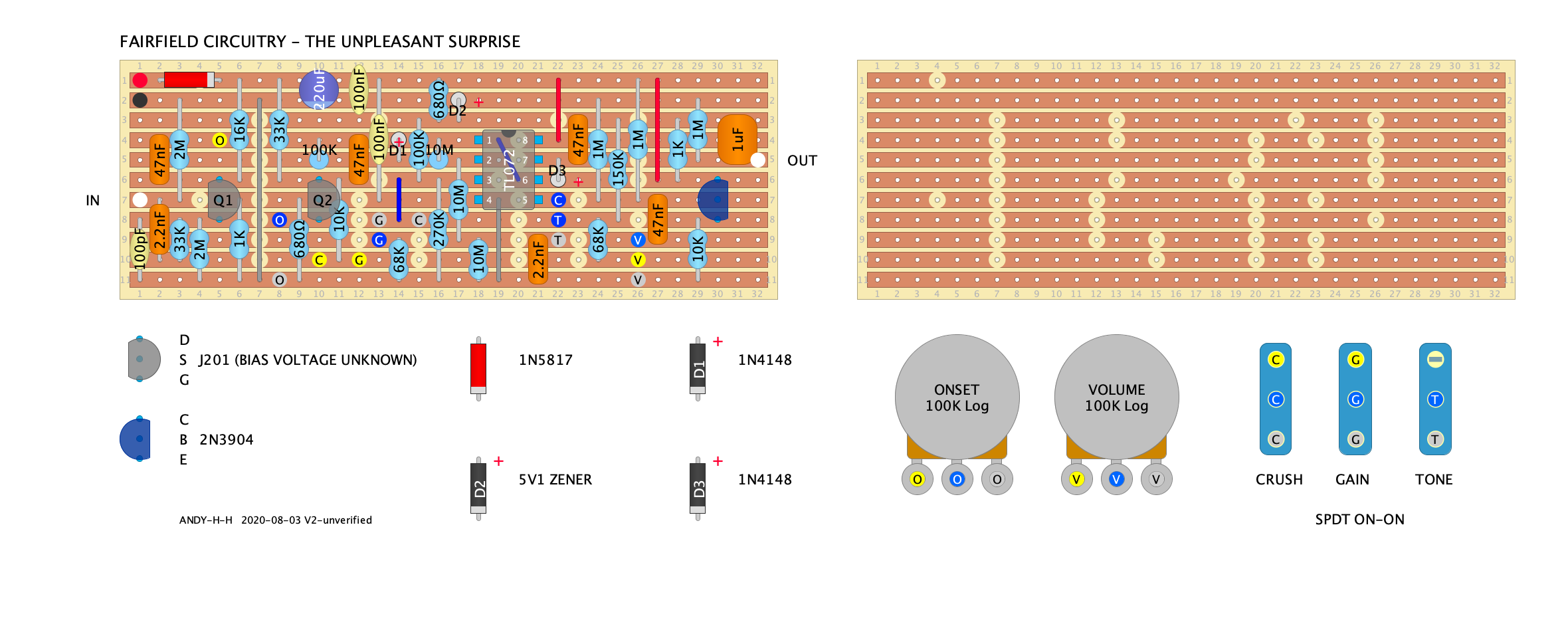
FAIRFIELD CIRCUITRY - The Unpleasant Surprise
123


123
|
This post was updated on .
Hot off the press (or off Pedal PCB in this case) Currently unverified - I have checked the schematic a few times, but I've also been staring at a screen all day...
 EDIT: version 2 - i missed the jumper between pin 1 and 6 on the previous.  PS the layout below looks better by the way. PS the layout below looks better by the way.

|
|
This post was updated on .
If I hadn't waited my afternoon to publish the layout I jst drawn I would have published it before you.
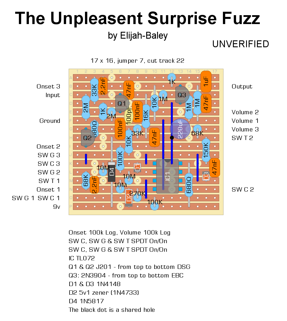
  This is still UNVERIFIED, too.  Let me know if you see mistakes. Edit: Indeed, I found big mistakes, so I taken off my layout. Then I reposted it with correction. Tell me if you see something wrong.
I build pedals
|
Re: FAIRFIELD CIRCUITRY - The Unpleasant Surprise
|
just breadboarded this and it's an immediate YES, but I was distraught to discover that despite having the choice of TWO awesome layouts with different aspects already available, I have only a very meagre stash of smaller vero bits and none big enough to build these layouts..... i have literally spent hours doing a very crappy inferior job to get it all to fit on the largest (23x12) i have so I can build it immediately.....
are either of these two verified yet, and is anyone thinking of doing their first hammer stamp legends in slightly cheeky tribute? |
|
I haven't built this one yet - I've been distracted with some other projects.
 It's on my to do list. I've checked the layout a few times against the schematic from Pedal PCB, pretty sure it's OK. I might have to bump this a little higher on the build list if you give it a big YES on the breadboard. |
Re: FAIRFIELD CIRCUITRY - The Unpleasant Surprise
|
In reply to this post by nocentelli
Hello!
I’ve attempted to assembled this layout (the elijah-baley layout) with limited success! I’ve owned this pedal and am quite familiar with how it sounds and operates. The best way to describe how my attempt sounds is very gated... like its being starved of power. The pedal actually operates and functions as it should… all the switches and knobs change the signal as they should however its very very gated … the onset pot needs to be all the way CW to get any signal through… I also have to dig into the guitar to push the signal through. Im fairly confident ive populated the board correctly and very carefully… ive tripled checked for solder bridges etc.. Im using a circuit testing pedal that definitely works fine.. Ive used all the correct components.. although for the IC I used a TL072CP… not sure the CP makes any difference? I didn’t think it would. I’ve listed all the values below… hopefully there is something obvious that stands out…! In some areas you’ll notice two different values.. the changes are in response to the gate switch. BTW, ive also put up a post in FSB debugging support... although I thought it might be useful here too. QQ1 J201s D: 6.9 S: .12 G: 0 Q2 J201s D: 2.6 // 3.7 S: .11. // .11 G: 0 // 0 Q3 2N3904 E: 3.15 B: 3.6 C: 8.9 D1 1N4148 Positive: 1.7 // 4 Neg: 1.6 // 3.8 D2 5v1 zener - 1n4733 Positive: 0 Neg: 5.25 D3 1N4148 Positive: 4 // 1.7 Neg: 3.24 // 8.4 D4 1n5817 Positive: 9.1 Neg: 8.9 IC - TL072CP 1: 1.6 // 4 2: 1.7 // 3.8 3: 1.8 // 3.8 4: 0 // 0 5: 3.7 // 3.7 6: 1.7 // 4 7: 8.4 // 3.3 8: 8.9 // 8.9 |
|
Hi
I used another layout for this one, but you'll want to alter the drain resistor on Q1 to get to around half your input voltage. That's the 16k resistor. |
Re: FAIRFIELD CIRCUITRY - The Unpleasant Surprise
|
Hey, thanks for the response... what value would you suggest? Although both versions of this layout here have the 16k connected to the Q1 drain..
|
|
True, both layouts have a 16k, but when dealing with Jfets you find that they bias differently.
Take out the 16k, put in a couple of sipp sockets and try different resistors. You'll need to increase the resistor value to bring down the drain voltage. When I built mine, with the 16k resistor the drain voltage was 3.62V, so I decreased the resistor value to 13K, which got me 4.65V. |
Re: FAIRFIELD CIRCUITRY - The Unpleasant Surprise
|
Great.. again, thanks for the response. I’ll give it a try and report back.
|
|
And I guess you should do the same with Q2 (33k resistor)
|
Re: FAIRFIELD CIRCUITRY - The Unpleasant Surprise
|
UPDATE
Ok, so here’s where im at. I’ve done my best to take notes and provide as much info as I can… hope someone can help me figure this out! :) I changed the Q1 drain from 16k to 33k which brought it down to 4.80 from 6.9. I changed the Q2 drain from 33k to 27k which brought it up to 4.65 // 3.45 from 2.6 // 3.7. Overall, its made a 70% difference from what it was although still doesn’t sound like it should. It still sounds overly spluttery and gated like its not receiving enough power? Or something else. I’ve updated the numbers below which have changed a bit since swapping the resistors. Where there are two numbers, the first number refers to the gate switch prongs 1 and 2, the second number is gate switch 2 and 3. Also, when the gate switch 1 prongs 1 and 2 are engaged along with the crush switch 2 and 3, there is no sound at all. I wonder whether theres a clue here with regards to the issue…. All other switch configurations produce sound. When gate SW 1and2 along with Crush SW 1and 2 are engaged and the onset is fully CW… its producing ongoing buzzing. Goes away when its turned CCW a little. When gate SW 2and3 along with Crush 2and3 is just a very gated fuzz… with the onset turn CCW 50% theres no sound. Again, thanks for your help dudes! QQ1 J201s D: 4.8 S: .12 G: 0 Q2 J201s D: 4.65 // 3.45 S: .11. // .11 G: 0 // 0 Q3 2N3904 E: 3.15 B: 3.6 C: 8.9 D1 1N4148 Positive: 1.7 // 4 Neg: 1.6 // 3.8 D2 5v1 zener - 1n4733 Positive: 0 Neg: 5.25 D3 1N4148 Positive: 1.76 // 4 Neg: 8.4 // 3.2 D4 1n5817 Positive: 9.1 Neg: 8.9 IC - TL072CP 1: 1.76 // 4 2: 1.61 // 3.8 3: 1.8 // 3.8 4: 0 // 0 5: 4.64 // 3.7 6: 1.7 // 4 7: 8.4 // 3.3 8: 8.9 // 8.9 |
|
Have you checked for solder bridges, holes/components misplacements...?
Your voltages look odd For example, Q2 drain should be stable, and Q3 base should be 4.45 (voltage divider) |
Re: FAIRFIELD CIRCUITRY - The Unpleasant Surprise
|
Hey alltrax
I've been pretty thorough looking for solder bridges and double checking it all looks as it should.. I could go over it again. I was pretty careful when populating the board .. Re Q2, you mean the figure should remain the same irrespective of the gain switch? Re Q3, is there something specifically I should be on the lookout for? Cheers |
|
The gain switch should not alter the voltage Q1 &Q2 drains are seeing.
For Q3, the base is connected to a voltage divider (see the schematic with the 2 1M resistors, one connected to VCC, to other 1 to ground. So Q2 base should see VCC/2 which in your case is 4.45v). There could be somewhere a tiny solder bridge, something it's very difficult to see, you could knife the notches between the copper rails |
|
I drawn the layout because there's a friend of mine who could like it, but he still doesn't need it and I'm still waiting to build it. So, though I didn't see any mistake, it could be faulty
You said: "I changed the Q2 drain from 33k to 27k which brought it up to 4.65 // 3.45 from 2.6 // 3.7." But with a smaller resistor I think you should gate more voltage, not less. A random video: https://www.youtube.com/watch?v=qlbVtkG7HcU and this fuzz is very gated. I assume you saw some video demo. Is your built even more gated?
I build pedals
|
Re: FAIRFIELD CIRCUITRY - The Unpleasant Surprise
|
hey Fx-Fidden - thanks for chiming in :)
I could have written that clearer.. so I changed the resister from 33k to 27k which resulted in more voltage..it changed from 2.6 // 3.7. and went up to 4.65 // 3.45. thanks for the link... im familiar with the pedal as I used to own it. I had a decent play with it earlier and its sounding pretty close, maybe not as full.. not sure. However, i did discover that the crush switch doesn't work at all.. it has no impact on the sounds or character of the signal except in a specific configuration with the gain switch, it kills the signal (I mentioned this above in my previous long response).... I wonder whether by fixing this it could potentially resolve the problem. |
Re: FAIRFIELD CIRCUITRY - The Unpleasant Surprise
|
In reply to this post by alltrax74
thats interesting ... as ive said, its feels like the pedal is just about sounding as it should.. its like it needs just bit more power or something.. what do you recommend I attempt to increase that voltage?
Also, I ideas where I should inspect re the crush switch not working (and cutting out the signal in a certain position)? |
|
I'm afraid I'm not sure what to suggest on your build, just to say that I built the layout on Dirtbox layouts and it works great.
|
Re: FAIRFIELD CIRCUITRY - The Unpleasant Surprise
|
hmmm - it looks like I might start over and use a different layout (the dirt box layout).. im wondering whether the figures ive produced are pointing at a faulty component at all?
|
|
Read this:
https://forum.pedalpcb.com/threads/calamity-fuzz-jfet-bias.3926/#post-31374 "I just fixed a Calamity for a friend. Once I got the right J201s in there, Q1's Vd was about 4V, Q2's Vd was 0.5V." Is it really means that the right voltage of the Q2 drain is 0.5V? Because, indeed, in my emulation software it's about like that. Maybe tha problem is around the Q2 drain. I'd like my layout will be verified, because it seems perfect and it's smaller than the dirt box layout one. And though it should be verified and sounds like it should, it could have a minor issue with one of the switch.
I build pedals
|
«
Return to Unverified Layouts
|
1 view|%1 views
| Free forum by Nabble | Edit this page |

