First tryout with strip boards
12

12
|
Hey all
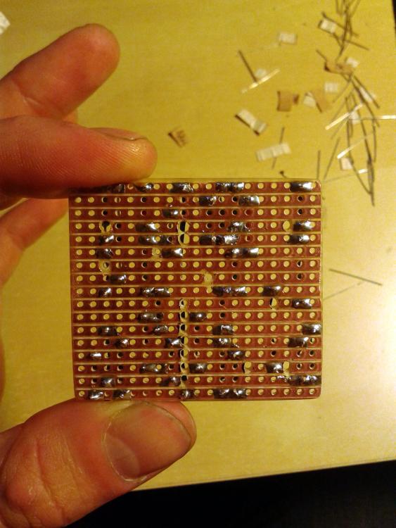
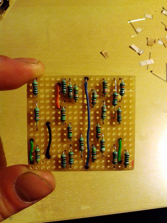
might be a very surprising question to ask AFTER I already placed some resistors on the board. I soldered the resistors according to the layout and hope that their position that is stated should not be mirrored with the layout of the cuts and links....  Its the layout of the Green Russian Big Muff you can find here (not the 1994 version): http://tagboardeffects.blogspot.de/2012/06/ehx-green-russian-big-muff.html thanks for your help and lets hope I dont need to do a lot of de-soldering and re-soldering right now. here are photos to show what I did:  
|
|
Administrator
|
No you've done it the wrong way, it's the bare board layout that needs to be mirrored when you're doing the cuts, that is shown as if looking through the board at the cuts in an xray.
But you're lucky because it's a transistor layout and so it doesn't matter because transistors are vertically symmetrical. So carry on as you are and remember for next time, because if it had been an IC layout you'd now be scrapping the board. If you check out some of the guides on the site, particularly the build guide: http://tagboardeffects.blogspot.de/2012/04/vero-build-guide.html you can compare the finished build with the layout at the top of the page and see all the components match up at the front. |
|
Administrator
|
i'm not quite sure of the question. but when you look at the posted layout, you're looking at it from the top (no copper). all your components, cuts, and jumpers should look exactly as you see it on the layout, it's not mirrored.
|
|
As Rocket said. If you were to print out the layout (at the correct scale) and stick it on the non-copper side, you could just poke the component leads through, and that would be your layout.
To do the cuts, you have to flip or mirror the image (looking at it a different way, the cuts are on the underside of the layout). I did exactly the same with my first layout before I realised, just before I started soldering fortunately. |
|
Administrator
|
me too. i ended up doing the pedal backwards. to get it to works. lol
|
|
Ha - braver than me - I binned the board and started again

|
|
In reply to this post by Tune Tone
So what are you guys suggesting for this project ? simply carry on as I started cause there is no IC involved ?
what about the transistors ? the placing of EBC.. ? donw want to end up fucking this up ;) thanks for your support ! |
|
Administrator
|
Just carry on and make sure you mirror it exactly. CBE is CBE whether you comes from the left or right, so just make sure you keep the same orientation of the transistors so the pins remain in the correct order, so basically don't mirror the transistors.
|
|
In reply to this post by Tune Tone
So far I experienced only with PCBs and kits for GuitarPCB.com or Musikding.de
I wonder what about the Led wiring in Greeny's Vero Build guide as you can see there is no resistors soldered to the Led, in this case won't the LED burn out ?? thank's! |
|
Administrator
|
There always has to be a current limiting resistor for the LED. Sometimes I include them on the board if there is enough space without having to add an extra column, but failing that most people just have it offboard, between 9V and the LED anode. Then the cathode goes to the stomp for switching as per the OFfboard guide.
|
|
Administrator
|
In reply to this post by dbat69
yea well, i think it's just being young, dumb, and refusing to let a small board beat me. the funny thing is, i built it 2 more times to compare components (ceramic vs poly caps). so i have 2 built boards sitting in my pile to be boxed again, at some point. |
Re: First tryout with strip boards
|
In reply to this post by Tune Tone
What I have done - was print out the vero from this site, turn the paper over and set it on a light so I can see through, then flip the vero over so that you are looking right at the copper strips.
This way, you are looking at the "mirrored image" but from the right side. This works for me and it has never failed. Just my .02 worth :)
Yeah, 220, 221. Whatever it takes.
|
|
This post was updated on .
Here's my process for prepping the vero board (need to include photos, but alas...):
(1) Cut out the board to the number of rows / columns specified. I sand the sides smooth so it's nice and square. (2) Place the board plastic side up, copper side down next to a printout of the vero hole pattern with the proper orientation. Mark the cut locations on the holes on the plastic side with a fat-tipped Sharpie back pen. (3) At your drill press, insert a 1/16 (or 2 mm) drill bit and drill through the board at the locations just marked for cuts. (4) Flip the board over to the copper side. Insert a dremel bit into your drill press with a 3/32" ball cutter (for engraving). You can use other bits, but the ball cutter works best for me. Drill the track cuts at the drilled holes so that the copper is cut across. You can of course use a hand tool for this. (5) Final (AND MOST IMPORTANT) step. Get your multimeter (if you don't have one, get one!) and test the continuity across EACH cut. Use a knife or round file to open the cut more if continuity is detected. Prepping the board usually takes me about a half an hour, but it is time well spent if done carefully. Also - I usually install the jumper wires first. It's not a bad idea to test these for continuity before populating the board. Sometimes, a bad jumper solder joint will come back to bite you (don't ask me how I know this...  ). ).
|
|
I do my boards similar to Frank.
I save the layout to my puter, open it in MS Paint, then Flip the image and save as another copy (as you can't read it as the text is reversed etc). THis then shows the layout view from the copper side  I mark both sides with a black marker pen. Then I cut the tracks with a hand tool (basically a small drill bit with a screwdriver handle - available from BitsBox) Just like Frank, I test each track to make sure the cuts are sound. THen do the links, test again and then sockets and test them. I check all my components (resistors & capacitors) before soldering them. I check the soldering with a Jewlers Loupe (magnafying glass with an LED light) - its great for seeing if I have a solder bridge. The bit I struggle with is the offboard wiring - this takes the longest to get just right, but I do it methodically, doing the stomp switch, LED and sockkets and ground wires first, before working the board connections. I just need to make my pedals a bit more presentable - I use a PTouch for the labels, but it would be nice to do some graphics, of more fancy text. But as I'm still learning all this, ... one step at a time. I need to do more tweaking, testing and learning what the components do in the circuit. THere has been some great stuff posted which I keep going back to, so thanks guys 
|
|
In reply to this post by Tune Tone
Thanks so much for all the tips !
I started a new board for another project I'm doing (Grind Costoms FX Tenebrion Reverb) I do have a multimeter and want to test the communication between the rows. Can you please tell more about it ? what state should my multimeter be on as well ? uld t check Voltage flow ? Resistance ? hFE ? Amps ? thanks ! yours newbie.. I mean truly! Assaf |
|
In reply to this post by Tune Tone
ok... think I got it. Multimeter should be on the beep sign. right ?
the beep reffer to a closed circle.. communication .. ? so I just make sure that all my cuts are cutting communicating trying to test the communication between them and the rows that below / beneath them ? cheers a. |
|
"Multimeter should be on the beep sign. right ? "
Yup. When you touch the probes together (short circuit) they should beep, and when you probe your vero board, put your probes on either side of a track cut. If it beeps, fix the cut and retest. Do this also for adjacent tracks (just in case some bit of copper is bridging the tracks). This takes only a few minutes to do but is essential to ensure a clean build. As I mentioned before, solder your jumpers first and test them also for continuity. It's good knowing that your foundation is sound before proceeding to laboriously solder the components. Note that if you touch on either side of a resistor, it appears as an open circuit (no beep). There is some (very small) minimum resistance below which the meter considers the probes to be short circuited. This can be useful if you suspect a solder bridge on a completed build as you can probe for continuity on adjacent tracks. |
|
In reply to this post by Tune Tone
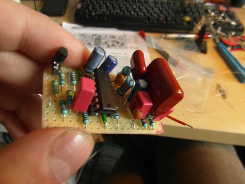
Here's the Reverb board...
can someone tell me if its safe to solder the on the legs of the Belton digital reverb unit ? I thought to use socket pins just to be safe but they are too small. Can it damage the unit ?? Im going to do the first off board wiring as well.. can you please assist me with Grounding ? when there is a mentioning to solder something to g round does it mean to the Ground row ( in the Grind FX reverb project would be the 2nd row from top..) or should it be connected to the ground connection of the DC in jack ? the ground of the DC should be attached to the stomp box it self, right ? thank's!! A. |
|
In reply to this post by Tune Tone

|
|
Administrator
|
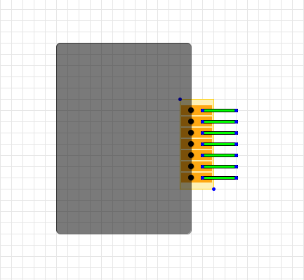
It appears to be all done in the correct orientation but we can't really tell much more than that. But I would suggest anyway connecting up the brick using another small piece of vero, that will make it easy to disconnect and reconnect should you need to, and give you a solid base to solder to rather than individually soldering wires to the pins.
Like this: 
|
«
Return to Open Chat
|
1 view|%1 views
| Free forum by Nabble | Edit this page |

