Fulltone OCD v3 questions
123
123
|
Okay, this is my first build. I bought my kit from bitsbox.co.uk, and i'm building it to one of lvlark's plans, see here
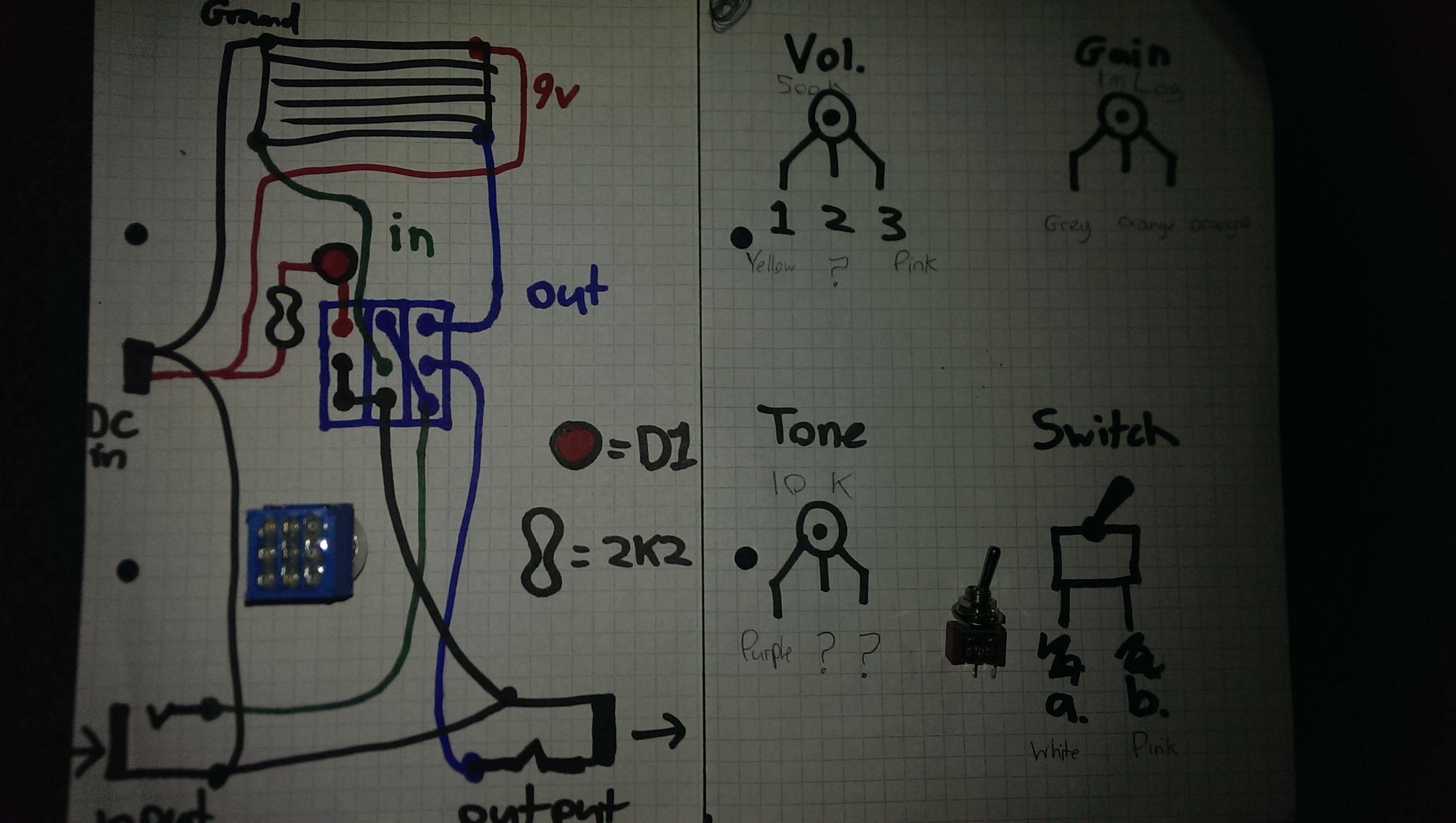
http://tagboardeffects.blogspot.co.uk/2012/02/fulltone-ocd-all-versions.html?m=1 I'm going through the process of colour coding my wiring to make things simpler for myself, however through this process i've come up with a few questions. 1. With the 2 position switch, how do i know which terminal is "A" and which is "B", or does it not matter? There arent any markings on the switch that give me any clues, both positions of the switch are marked "on", the only difference being one terminal is closer to the centre than the other. 2. When wiring my stomp switch, how do i know which way is "up" as it is represented on my diagram below? (lvlark's off-board wiring diagram) Again, no markings or anything to suggest which side is which. 3. The plan specifies a 500k volume pot, the one i have says b470k. Will this be a problem? 4. I've drawn a colour-coding diagram to save me time in case i get lost, what does terminal 2 on the volume pot connect to? Also terminals 2 and 3 on the tone pot? (Where i've drawn question marks) 5. What are "D1" and "2K2"? My guess was an led and resistor, if so, what would be suitable components? Please excuse my crude drawings, i tried to keep them as un-cluttered and legible as possible....  |
|
Also, what size wire should i be using for this? The more i type into google the more confused i get, so, i know that 22 seems to be popular, what diameter is that in metric?
|
|
Administrator
|
In reply to this post by El_Diablo572
Welcome to the forum
1. It doesn't matter 2. If you look at the threaded shaft of the stomp switch, there is a knotch on one side of the shaft. This will be pointing up or down. The solder lugs will be horizontal. It is the wrong direction in your photo 3. 470K will be fine 4. Always carefully read the notes at the bottom of the layout. It tells you that lug 2 of the volume pot is the output of the effect and connects to the stomp switch. Check the offboard wiring tab at the top of the page for more details if needed. Tone 2 and 3 connect to ground (also noted at the bottom of the layout) 5. 2K2 is a 2.2K or 2,200 ohm resistor. We write "2K2" instead of 2.2K because the decimal point can be difficult to see. I don't see any D1 on the layout, but the way you have the LED drawn in your diagram is correct |
|
Sorted, thank you very much mate. Feel like a bit of a dullard for not seeing the notes about the volume and tone terminals... My scrawly drawing looks a little more complete now...
Any ideas about what diameter of wire i should be using? |
|
Welcome!
Wire in fact is a matter of personal preference I think - I for example use AWG 24 stranded wire like this Cheap and does the trick. Some folks like solid wire, its great if you want to run it sraight to make it look neat - but imho its not so great since it tends to break if you bend it to often, and at least I do this all the time to make the wiring fit into the enclosure... And it has to be thin enough so you can put it through the holes in the vero board of course  And I've been told that blue sounds best 
|
|
Tanks man, i'm just a little worried that the wire i have is perjaps a little thin (very similar, if not the same as the wire you'd find in a 9v battery snap) most of the photos i've looked at on here show much thicker wire than what i have, some appear to be shielded too.
It probably isnt much of a big deal but my enclosure is going to end up pretty special, my components are all very spaced out and i need to do some pretty long runs with the wire, so i thought best to ask and be sure. My only issue now is identifying all these resistors.... Thanks for all the help lads, i promise when it's done (and hopefully working) it'll be worth all the hassle and silly quetions, Not only am i new to pedal building but i'm a complete n00b with electronics too, so all your help and advice is greatly appreciated. |
|
I'm having a nightmare identifying these resistors. My kit arrived with just a bag full, no tags or labels or anything to speak of, and one odd one out which doesnt even appear to be a part of my kit, the component list specifies 9 different types and i count 10. All are green except for this slightly larger blue one...
The problem is identifying the colour rings on the resistors themselves. Reds and oranges and brown are all just a slightly different shade from one another, and gold is just another shade of brown also, yellow looks like green, etc etc, when i do find what i believe to be a colour match the colours read in the wrong order, they all have a black ring around them even though my colour chart says only about 4 of them should have a black ring.... What do i do, short of buying more of each individual component and hoping they're labelled this time? |
|
Blue resistors are harder to read (ime) than the cheaper cream coloured, lower tolerance carbon film type, so go for those if you give up on the parts supplied. I'm slightly surprised they're not marked, since I have bought from bitsbox for years, and their service is usually great. It's be worth emailing, they might even send you some labelled ones since it's only a few pennies in parts.
That said, I would urge you to persevere with sorting them since there are only 9 unique values and it's something you'll find very useful if you end up making more pedals. I'd start by trying to pick out the 1M and the (four?) 10k resistors. Both values will start with brown-black (for 10-) but the rest of the code will be different for one of them. Likewise, there will be a 33k and a 39k, both will start with orange but one will be pink next (39k) and the other will be another orange for the second stripe: The rest of the code will be the same (i.e. same order of magnitude). The 22k will be identical to the 33k, but will start red-red instead of orange-orange. There will be a single 18k that will look just like the multiple 10Ks, but will be subtly different, starting brown-grey instead of brown-black etc etc |
|
Test them with your multimeter! Make sure you aren't holding on to them when you do, though.
Through all the worry and pain we move on
|
|
I'd also recommend using a multimeter, I find it very hard to read the color codes, too. If your planning to spend some time with this hobby a multimeter is worth every cent (they're not that expensive anyway): it makes it so much easier to identify components, test for continuity and read voltages during debugging...
|
|
I've identified the 10k's because they are all the same, that was pretty easy. But according to my list of colours, 10k should be brown black orange and gold, brown red and gold all look the same shade of colour and i have two black lines next to each other....
Also, my list says the 39k should be orange white orange gold, but you said orange pink..? (I got my values from google, so chances are i may be wrong and need to go over this again...) I think i'll just go with the multi meter idea, i spent the entire day trying to identify them by eye yesterday and i'm no further forward |
|
After looking at them again, i think the problem is that the paint or ink used to mark the rings is a little thin. The base colour of the resistor (dark green) appears to be bleeding through the finish of the markings, and effectively making the colours a little more muddy than they should appear
|
|
In reply to this post by El_Diablo572
Yep, you're right, white is 9, my bad. I like this calculator: http://www.electronics2000.co.uk/calc/resistor-code-calculator.php But a multimeter may be a better approach if you can't distinguish the colours |
|
Yeah, as you say, the issue here is distinguishing the colours. Some appear to be slightly worn, some appear to have a thinner coating of paint than is perhaps required, and they're so damn small!!!!
|
|
This post was updated on .
Bought a multimeter (a cheap draper one but it's guaranteed and seems to work fine)
All my 10k's appear to be good, all reading 9.97, except one which i worried i might have fried with the soldering iron, this one reads 10.2. Problem? Seems the odd one out was actually the 2k2, the extra one (at the bottom of my photo) gives me a reading of 470 in the 2000m range. Would that be 500k? Not that it matters, i have what i need now, best warm up the iron! EDIT: referring to my plan i've actually found a 470k, so that's where my mystery resistor goes. seems the component list on the bitsbox website is missing this, as that's where i got my list from |
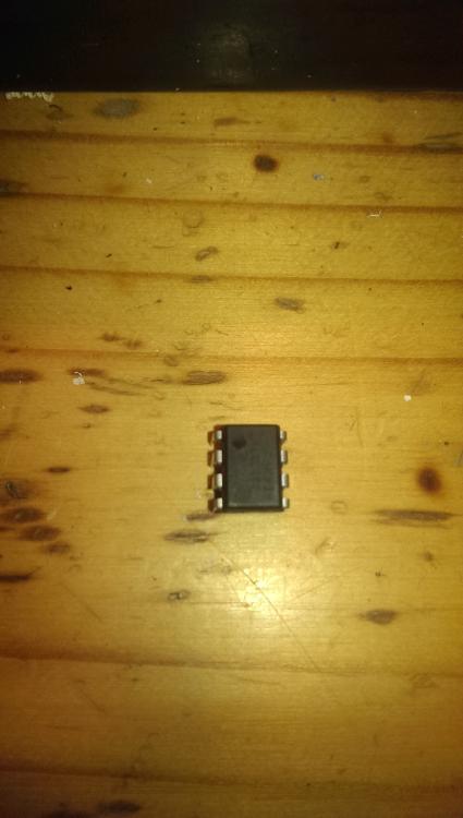
 And we're basically done, except i dont know which way around to fit the op amp. Suggestions? |
|
Administrator
|
The IC needs to be installed as shown in the layout with the crescent shaped indectation facing the top edge of the board
It's best if you use a socket for ICs and not a bad idea to use sockets for the mosfets which are extremely sensitive to static discharges. I know you said you got this as ankit, so maybe they didn't include sockets |
|
No, no sockets unfortunately. Also, my op amp doesnt have a semi circle indent like you say, i noticed that on the drawing but couldnt find one.

|
|
Administrator
|
actually your IC does, it's that dot. it indicates the top of the IC. some will have a dot like the IC you have and some will have the half circle like you see in the layouts.
|
|
Administrator
|
In reply to this post by El_Diablo572
Sorry, I was gonna mention the dot, but decided not to in case it was just irrelevant info. The IC will have the crescent, dot, or both. In any case, that mark denotes pin 1, and must align with the crescent in the layout.
One tip with the IC.. I have never burnt one out with my soldering iron, they are pretty resilient, BUT.. try not to hold your iron on the IC for more than a few seconds. Also, after you solder one pin, wait for the IC to cool down before you solder the next pin. |
«
Return to Debugging
|
1 view|%1 views
| Free forum by Nabble | Edit this page |

