Just can't figure it out!
12


12
|
I'm new to pedal building, new to veroboard...I found an easy schematic of a fuzz pedal, put it together and soldered it. All I can get is a clean sound, no fuzz! I have no clue where to put the cuts. Any ideas?
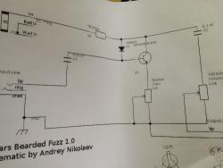 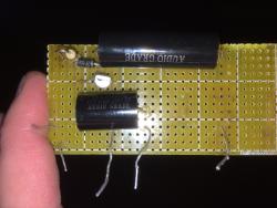 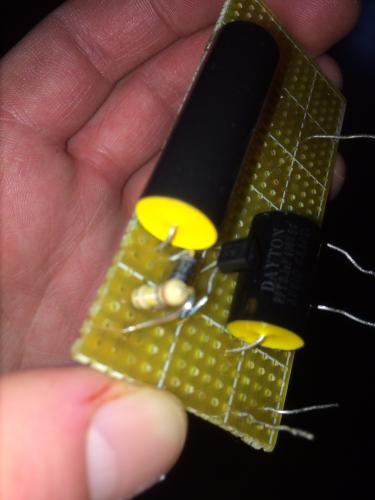 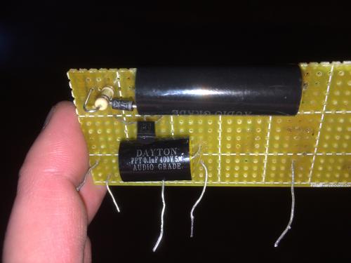
|
|
Administrator
|
Your photos don't really show any details of the board. We'd need a shot of the underside and maybe a better shot of the top.
It looks like all of the transistor legs are on the same strip, caps are all shorted to the same strip, and the resistor is shorted on one strip. You need to at least put a cut between the resistor legs, between the cap legs, and between the tranny legs, otherwise you have everything shorted. A better way to go would be to turn the components so they're oriented vertically rather than horizontally |
|
In reply to this post by Southcity1983
Try one of the simple one-knob fuzz layouts here (like the Colorsound Fuzz below) and go step-by-step. The cuts and links are all marked, as is the control wires and component placement. Good luck!
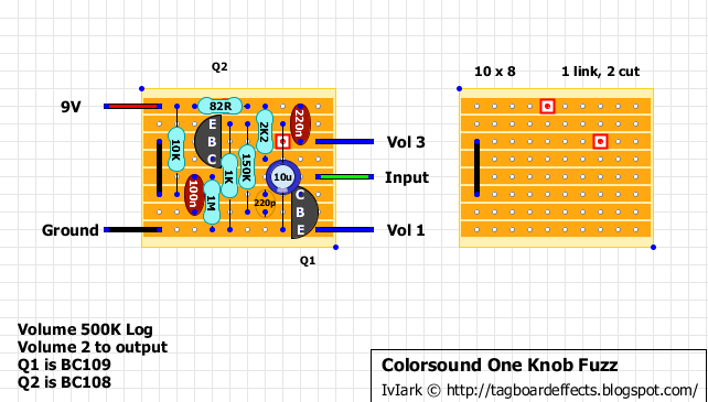
|
|
In reply to this post by Southcity1983
You should work with some vero layouts first to understand the concept. Making a schematic into a vero for your first build is pretty ambitious!
Anyway, when the legs of the same component are on the same row, there should be a cut between them. When they are spanning across rows there is no problem. As such 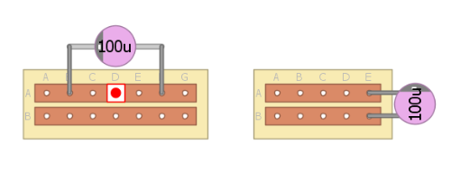 I see you bought some pretty costly parts, without really knowing what to do with them. You just gonna get frustrated and/or blow them up (no joke, real chemical hazard there). Take it easy with little steps like we all did and you'll get there in no time  **edit** 2 answers already while I was typing this. I love this forum and these guys :D |
|
As far as I can see, you've constructed the circuit topology correctly according to the schematic (no cuts should be required) assuming your component values, offboard wiring (alligator clips?) and your transistor pinout are correct.
You say you're only getting clean signal. Do the fuzz and volume controls do anything (assuming that's what they're called as I can't read your schematic)? Are you getting more volume than in bypass? I'm not familiar with this specific circuit, but I wouldn't expect great amounts of fuzz from it. It looks like a simple 1-transistor boost with one feedback clipping diode. It will probably sound more like a dirty boost, though without the component values I can't estimate how much gain you should get. |
Looks like a bazz fuss. Assuming it's a 1k gain pot off the emitter, and the collector resistor is 100k (with a normal Bjt), it should be pretty fuzzy. Whatever, we need to see better photo's of the copper track side to diagnose further. |
|
Right you are, my bad.
If the circuit works but isn't fuzzy, the gain pot might be too big, though it should still fuzz at high settings. I'm less suspicious of the back of the board than of the component values and the offboard wiring. But you're right, it would be good to see the back of the board too. |
|
Administrator
|
I'm on my iphone and zoomed in on the schematic picture. I can only make out that it's a something bearded fuzz 1.0 and who drew it up. Tried searching for a better pic of it and didn't come up with it, but did find out that there are a lot of pedals with beard in the name.
|
|
In reply to this post by Southcity1983
 First off, let me say, WOW! You guys are great! I was expecting some bashing and short useless responses; I got the opposite. First off, let me say, WOW! You guys are great! I was expecting some bashing and short useless responses; I got the opposite.
When I made this post I did it with haste, I should've been a bit more informative. I will include some pics to help out. I am currently enrolled in an electrical engineering school, so I have pretty much any part at my disposal for cost. I bought 4 of every part, why buy one when you can get 4 at cost? So far this pedal is running about 18$ including pots, jacks, LEDs, wires etc. I first put this together on a breadboard and it sounded great. I play out of a Les Paul and a vintage Fender Deluxe Reverb, so it was a warm fuzztasticly awesome sound! Once I got it off of the breadboard onto the Veroboard all I got was a clean boost, no fuzz...when turning the 5K pot i get nothing. So, I went back to square one. I measured resistance at all the pots and got perfect results, checked all wires for breaks, checked solder point, got the data sheet on the transistor, checked voltage across capacitors etc. So i built it all again. The only difference from the schematic to build is that I used a MPSA13 instead of MPSA18. 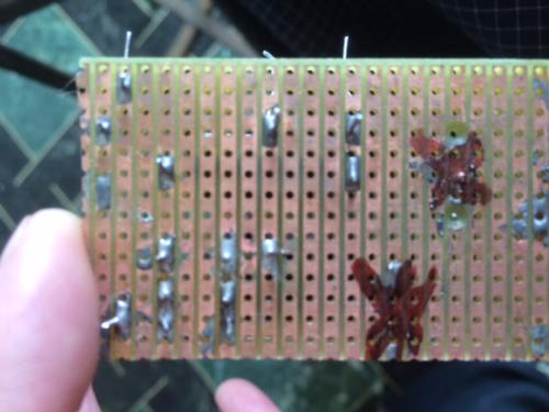 As you can see on the underside, it looks like a mess...I flipped the board over and put it back together using the opposite end of the board, the "X's" are not being utilized at all and have zero points connecting to the circuit. I used a bigger board than needed for this exact reason, measure once, build twice, right? I checked all the tracks for solder jumpers under a magnifying glass, all is well as far as that is concerned. If need be, I'll go from square one, a complete rebuild. As with most of us, I'm sure that doesn't sound like fun. I still have to wire in my foot switch, LED, and power supply... Somewhere from breadboard to veroboard it got messed up. 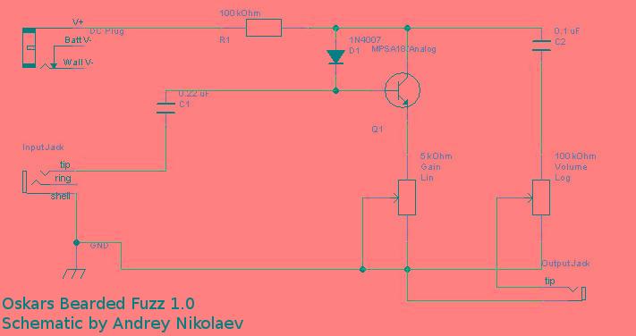
|
|
Those caps are so insanely huge, I can't figure out the connections of the reverse of the board, but assuming all the connections are correct (and you do sound like you know how it is supposed to hook up), my only thought is that the original bazz fuss had a plain old BJT (ie. like your original cool sounding breadboard version) with a 100k collector resistor. The next version that uses a darlington MPSA13, drops the collector resistor to only 10k. If you've kept it at 10k, it might not work as advertised (though I would have assumed the gain would be too high, not too clean so it may not be the cause of your woes).
|
|
Administrator
|
In reply to this post by Southcity1983
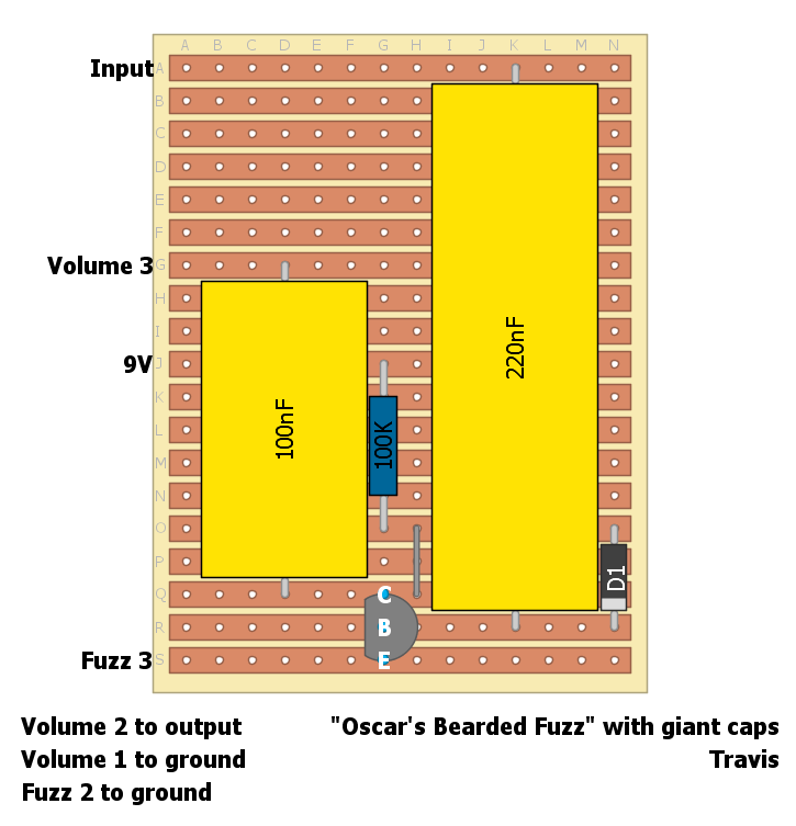 I'm having a hard time understanding whats going on there so I just made this. It has no cuts but one link. Make sure the pinout of your transistor matches the CBE labels not necessarily the orientation of the flat side |
|
Man! I Think you just made my day! I'm assuming for ground to use the strip above the 9v spot? If that's where it should be then we are in business. Where do I get a program like that?
Much obliged friend ! James
Sent from my iPhone
|
|
Administrator
|
There is no ground connection needed on the board itself, but fuzz 2 and volume 1 go to ground. And your input and output jack sleeves should also be grounded, and the enclosure as well if you box this up as a stompbox. In that case check the offboard wiring tab at the top of the page here
|
|
If you are using an MPSA13, the transistor needs to be flipped 180 degrees compared to the diagram for the pinout to be correct. Also, consider trying a 10k rather than 100k for the collector resistor.
|
|
Administrator
|
In reply to this post by Southcity1983
By the way, the layout software is DIYLC which is free
https://github.com/bancika/diy-layout-creator/releases http://diy-fever.com/software/diylc/ |
Why oh why will this not work?!?!?!
|
In reply to this post by Southcity1983
Hey guys,
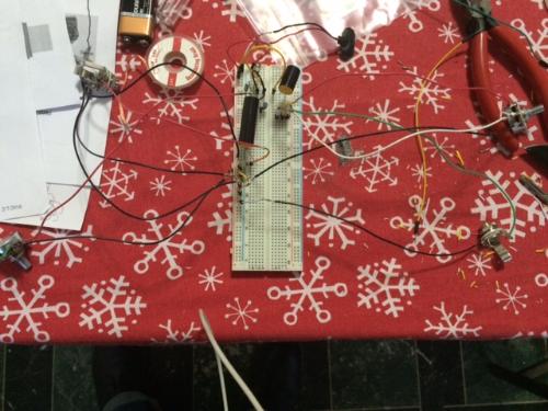
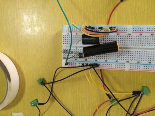
So it's been a while since I've been able to post my progress. To say the least it's been frustrating. Since my last post I have gotten a higher grade solder and Veroboard. I have re-soldered all of the pots, inputs, and out puts. I followed the Veroboard lay outs that were given and all I get is a clean channel. I have checked for solder bridges and there doesn't appear to be any. As far as the way this board looks now: The pins sticking out are where I'm alligator clipping to the inputs of the pots and input/outputs, and power. As for ground, I'm running the ground of the battery to the breadboard and hooking up all the grounds to it. In the picture what you see is all the grounds hooked up, as well as the prototype on the breadboard. The prototype is in shape way of form hooked to the circuit board. Like I said before, the prototype works awesome! The board I built doesn't work at all. After some tweeking I still get a clean channel only. Any ideas? 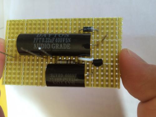 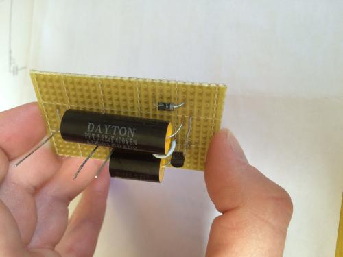 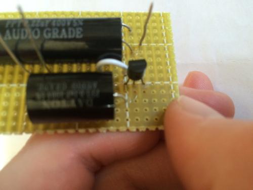 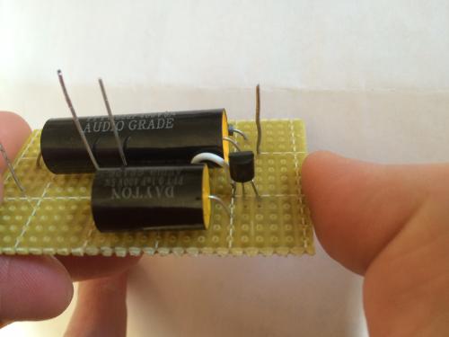 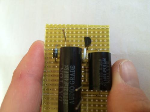 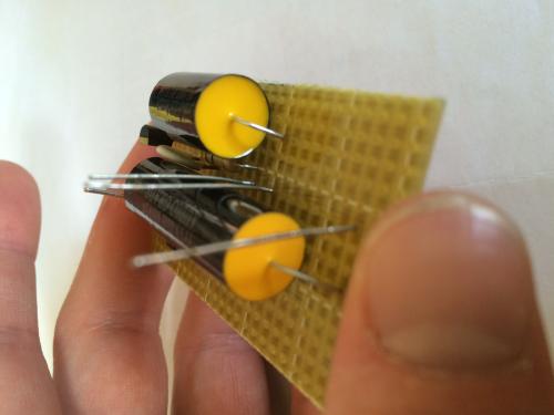 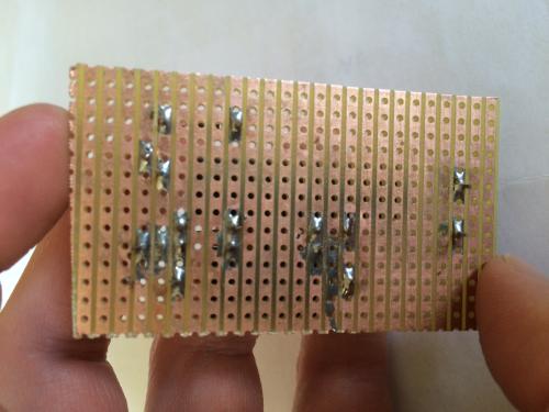 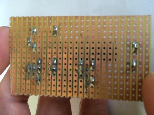 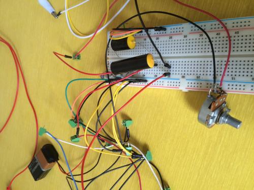 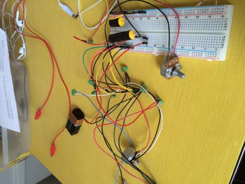 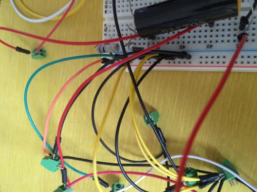
|
|
Can we see some pictures of your board hooked up for testing?
The board itself looks fine. If the circuit works on the breadboard but your vero doesn't, then the problem is likely to be in the offboard wiring. |
Re: Why oh why will this not work?!?!?!
|
Yep, I'll get to as soon as I get some free time. Probably next week, thanks for the help, I really want to get this thing working.
James
Sent from my iPhone
|
Re: Why oh why will this not work?!?!?!
|
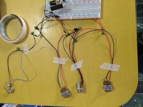
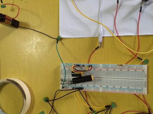
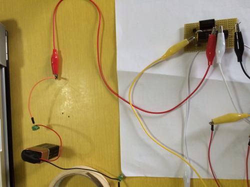
So here we go again, all of this works when hooked up to the breadboard, but when I hook it up to the Veroboard I only get a clean sound. Basically how I have this hooked up is I’m using alligator clips that are connected to wires I have soldered onto the Veroboard, when this works this is where I will be hooking up the pots and input/output. I have hooked up the negative terminal of the battery to the negative row on the breadboard and have connected all of the grounds for the potentiometers and input to that same grounded row. What you see on the bread board , the resistors, caps, diode etc are not hooked up to positive or negative terminals of the breadboard, they are just there so I don’t have to keep putting them back on and off. So, from what I can tell, there has to be something that I’m missing going from the breadboard to the Veroboard. Any Ideas?
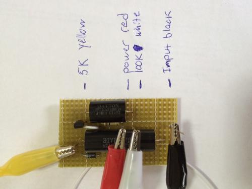 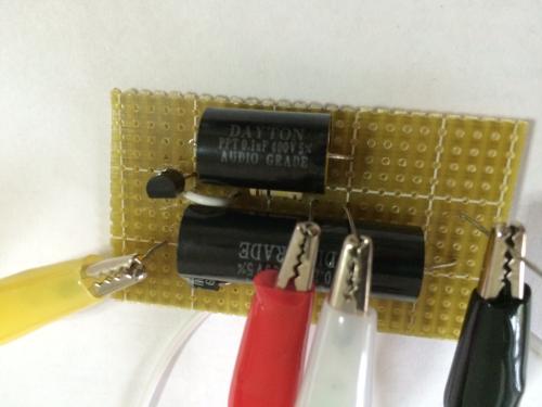 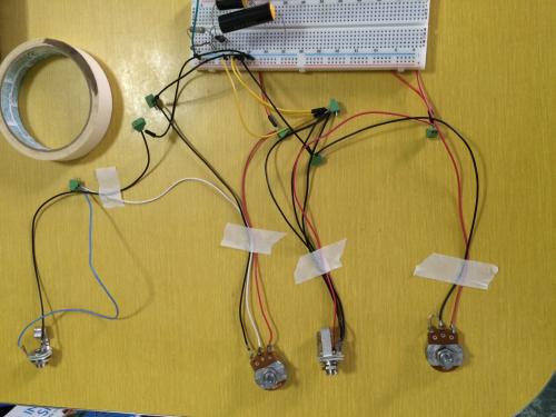    
|
|
The only glaring error I've found from the photos is that both of your pots are wired backwards. Don't feel bad, though. The schematic has them wrong, too. What happens when you adjust the gain control?
Clean signal from a fuzz with no bypass switch suggests wiring errors on the input and output jacks. But if the clean signal is boosted, that confuses things somewhat. Can you post close-ups of the jacks? Edit: All those green connectors make things hard to see as well. Have you tried plugging the wires from your jacks and pots directly into the breadboard? |
«
Return to Open Chat
|
1 view|%1 views
| Free forum by Nabble | Edit this page |


