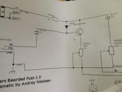
Just can't figure it out!

12

12
Just can't figure it out!

|
Re: Just can't figure it out!
|
Administrator
|
Re: Just can't figure it out!
|
|
Re: Just can't figure it out!
|
|

Re: Just can't figure it out!
|
|
Re: Just can't figure it out!
|
|
Re: Just can't figure it out!
|
|
Re: Just can't figure it out!
|
Administrator
|
Re: Just can't figure it out!
|
|
 First off, let me say, WOW! You guys are great! I was expecting some bashing and short useless responses; I got the opposite.
Re: Just can't figure it out!
|
|
Re: Just can't figure it out!
|
Administrator
|
Re: Just can't figure it out!
|
|

Re: Just can't figure it out!
|
Administrator
|
Re: Just can't figure it out!
|
|
Re: Just can't figure it out!
|
Administrator
|
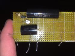
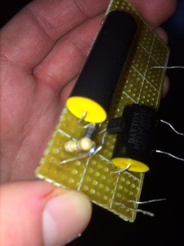
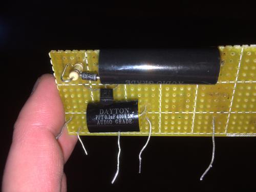
Why oh why will this not work?!?!?!
|
|
Re: Why oh why will this not work?!?!?!
|
|
Re: Why oh why will this not work?!?!?!
|
|
Re: Why oh why will this not work?!?!?!
|
|
Re: Why oh why will this not work?!?!?!
|
|
| Free forum by Nabble | Edit this page |