Looking for a crazy fuzz?

classic Classic list List threaded Threaded
24 messages Options
12
Reply | Threaded
Open this post in threaded view
|

Looking for a crazy fuzz?

Kinski
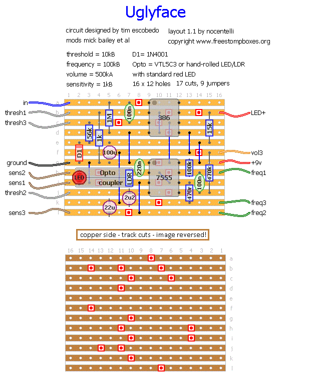
After getting frustrated with my DBA Robot build, I decided to move on for the moment. So I slapped together Tim Escobedo's Ugly Face.

This thing is incredible. So many sounds. Kind of like a Fuzz Factory, but not at all. It can do auto-wah-ish stuff, AMAZING sub-ocatave tracking, fixed-wah, and so much more. All in a blanket of nasty fat fuzz. Plus, it oscillates if you want it to, with a huge pitch range.

I have yet to box mine up. But when I do, its home will be in a shiny new 1590A.

Vero layout attached!

Oh yeah, the layout does not mention it, but:

VOL 2 to OUTPUT
VOL 1 to GROUND
Reply | Threaded
Open this post in threaded view
|

Re: Looking for a crazy fuzz?

GoranP

Sounds cool! I love lfo circuits so I may go with the modded one, though...
Reply | Threaded
Open this post in threaded view
|

Re: Looking for a crazy fuzz?

alltrax74
In reply to this post by Kinski
Are you really gonna fit this in a 1590A enclosure with 4 pots, even 9mm ones ?
Reply | Threaded
Open this post in threaded view
|

Re: Looking for a crazy fuzz?

Olav
It fits a cardboard box fine; https://www.youtube.com/watch?v=rO94z7RQMSg
Reply | Threaded
Open this post in threaded view
|

Re: Looking for a crazy fuzz?

alltrax74
In reply to this post by Kinski
Lol
Can't imagine the size of the pedalboard
Reply | Threaded
Open this post in threaded view
|

Re: Looking for a crazy fuzz?

nocentelli
In reply to this post by alltrax74
It will certainly be tight in a 1590A - 12 holes x 2.54mm = 30.48mm. I thought 1590A was around 30mm wide
Reply | Threaded
Open this post in threaded view
|

Re: Looking for a crazy fuzz?

Kinski
Nah, its not so bad. I can fit 14 holes if I sand down the edges carefully. 12 holes fits fine. I've done many 1590A builds with four 9mm pots!

Madbean made a very useful document on 1590A builds.
http://madbeanpedals.com/downloads/BabyBoardGuide.pdf


Reply | Threaded
Open this post in threaded view
|

Re: Looking for a crazy fuzz?

alltrax74
Very interesting, thanks man for the link, i'm gonna stock up on 1590A
Reply | Threaded
Open this post in threaded view
|

Re: Looking for a crazy fuzz?

Kinski
Done.

Reply | Threaded
Open this post in threaded view
|

Re: Looking for a crazy fuzz?

alltrax74
Ah ah looks cool but we need a pic of the inside
Reply | Threaded
Open this post in threaded view
|

Re: Looking for a crazy fuzz?

Kinski
The Guts:


With a little paper between the board and the jacks.
Reply | Threaded
Open this post in threaded view
|

Re: Looking for a crazy fuzz?

Madferret
Wow, seriously impressed with how you can do these 1590A builds.  One day I'll have to give it a go, for now though I think I'll stick with the Bs and BBs.
Reply | Threaded
Open this post in threaded view
|

Re: Looking for a crazy fuzz?

alltrax74
In reply to this post by Kinski
Very neat
Where do you source your 9mm pots ?
Reply | Threaded
Open this post in threaded view
|

Re: Looking for a crazy fuzz?

Kinski
http://www.smallbearelec.com/servlet/StoreFront

Wish Tayda would start stocking these.
Reply | Threaded
Open this post in threaded view
|

Re: Looking for a crazy fuzz?

alltrax74
Reply | Threaded
Open this post in threaded view
|

Re: Looking for a crazy fuzz?

peeps
In reply to this post by Kinski
That diode orientation looks wrong- is it backwards and shouldn't it be in series with the 100uf cap?
Reply | Threaded
Open this post in threaded view
|

Re: Looking for a crazy fuzz?

induction
That's a polarity protection diode.  It's done correctly.  The cap is for power filtering, and is also correct.  

Are you comparing this layout to the one by pinkjimiphoton?  I don't know why he arranged his that way, but I suspect it was an accident. It doesn't provide polarity protection and it only filters the positive half of the voltage ripple.
Reply | Threaded
Open this post in threaded view
|

Re: Looking for a crazy fuzz?

peeps
Yes & the original schematic.  I've noticed other Escobedo schematics done that way, including the PWM.  So are they both right?
Reply | Threaded
Open this post in threaded view
|

Re: Looking for a crazy fuzz?

induction
The pinkjimiphoton layout and the original schematic are slightly different.  jimi puts a forward-biased diode in series with a cap to ground, and takes V++ directly from the power supply.  This is odd and probably a mistake.

The original is almost the same, but takes V++ from the junction between the diode and the cap.  This is common method for supplying polarity protection (diode) and AC filtering (cap).  The layout in the OP has a reverse-biased diode to ground in parallel with the cap to ground.  This is another common method.

AC filtering:
Cheap power supplies don't entirely remove the AC ripple from the mains power.  In many circuits, the small amount of remaining 60-cycle hum can be amplified, which is irritating.  A large-ish cap to ground (10uF or greater, usually) can reduce this hum by sending the ripple to ground.  A 100R resistor between the filter cap and the power supply works even better (it's basically a low pass filter, with a very low corner frequency).  If a voltage divider is used for biasing a transistor or op-amp gain stage, the divider will have to be filtered as well, since the hum will be amplified along with the signal.  This can require some slight re-engineering if the circuit is designed for battery use only (orange squeezer, for example).  Using a regulated and filtered power supply generally makes this unnecessary, but I include it in my builds anyway.

Polarity protection:
A diode in series between the adapter and the V++ supply point protects against polarity reversal (using the wrong adapter or accidentally touching the battery to the wrong contacts) by stopping any current from flowing in the wrong direction through the circuit.  The cost is about 0.7V reduction from the supply voltage.  Whether this voltage drop has an audible effect depends on the pedal.  The diode also acts a little like a resistor and can enhance the AC filtering effect when used in conjunction with a filter cap.

A diode in parallel between the adapter and ground acts as polarity protection by shorting all reverse current to ground.  This works well for temporary reversals, and doesn't reduce the supply voltage at all.  The downside is that longer reversals (like using the wrong adapter) will cause so much current to flow through the diode that it will get hot and fail.  When it fails, it can either go open-circuit or closed circuit, both of which are bad news.  Open circuit means that the pedal is no longer protected from the reversed polarity and sensitive components (like IC's and polarized caps) will probably be destroyed.  Closed circuit means that lots of current will continue to run, heating up and ultimately melting the circuit board and other components, and/or destroying the adapter.  If the ruined diode melts before the adapter fails, you're back to the open-circuit scenario.

If the circuit can handle the voltage drop, I go with the series diode.

Sorry to go OT, but I hope it helps somebody.
Reply | Threaded
Open this post in threaded view
|

Re: Looking for a crazy fuzz?

peeps
All good stuff.  It would be really cool to see all of those examples represented schematically or pictorially on vero... Anyone up for an educational layout of all possible polarity protection options?
12