PNP pedal Problems
12
12
|
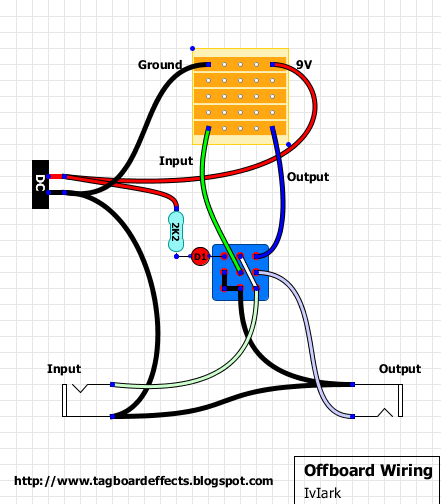
Every PNP layout I try never works and I don't know what I'm doing wrong? Is my wiring wrong? I'm currently working on this layout: https://4.bp.blogspot.com/-7SORlp_pZf8/UTNyUHTi_cI/AAAAAAAAB7g/kFO1EW7JaVs/s1600/DAM-1966-Compact.png and I'm using this switch diagram thinking that was the problem: http://www.generalguitargadgets.com/pdf/ggg_sw_3pdt_tb_pnp_dcj_gi.pdf
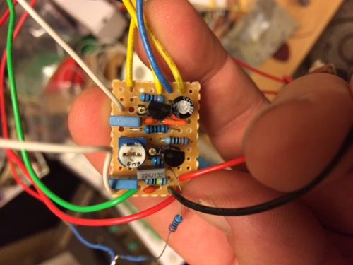
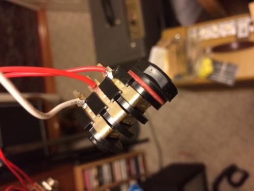
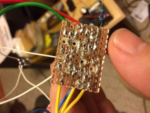
and here are two pictures of my build: |
|
In reply to this post by kdj432
Does it not work at all? I've had trouble with those high gain fuzzes myself. My first 5 circuits were the DAM Meathead and Coloursound One Knob Fuzz and none of them worked properly. Now I think it was just an hFe or bias issues. They would screech in oscilation or would be so gated that you'd almost need a hammer hitting the strings for the signal to pass through the effect. If the signal is not passing at all, then it's probably some error somewhere.
I'd suggest posting the underside of the board, running the knife between your tracks, triple checking pinouts of your trannies and posting your transistor voltage readings.
aka Dead Eye
|
|
yeah, I'm not getting any signal through it. I've built some Rangemasters and a Tone Bender MKI and none of them work. I'm using 2n2907 transistors in this layout just to test it and the pinouts are correct. I'll give it another pass with the x-acto knife and post another pic tonight.
|
|
your not powering these with your normal 9v power supply are you? you do know they need a -9v supply and +ground
If it wasn't for this website I would definitely have a life.
|
|
I'm using a battery.
|
|
Administrator
|
I think what dexxy is asking how you wired the batter. You need to wire the positive of the batter to the ground and negative to the power. PNP means the power is reversed from normal, ie: 9v is goes to ground on the board, and ground goes to power creative a reverse of flow of electrons so to speak.
|
|
I hope so, I'm following the layout and the wiring diagram that I posted above.
|
|
In reply to this post by kdj432
Using your multimeter measure the voltage from the -9v row to the ground row, if it reads as a positive voltage (ie, 9v displayed) then you need to swap the battery wires, if it shows as a negative voltage (-9v displayed) then your problem lies elsewhere.
If it wasn't for this website I would definitely have a life.
|
|
yeah, that checks out. I've tried adding a Negative voltage inverter along with the basic offboard wiring that Mark suggests and still nothing. I've been using silicon transistors to test this out and I read something last night that said something about this circuit requiring Germanium so I threw some Ge's in there and still nothing. This is driving me nuts!
|
|
Administrator
|
What transistors have you tried?
|
|
the silicon test trannys were 2n2907 and the Ge's are OC44 and 2n404. (that's all I have on hand at the moment)
|
|
at this point I wish I could hand it off to somebody to check it over, I really want to figure out this problem, I'm obsessed with building a working Tone bender.
|
|
Administrator
|
hey man, don't give up on it. it's really part of the learning process. you'll learn more about circuits and how to get them working once its figured out. then you'll end up having pretty much every build working from the start.
the tone bender can be a little fickle, which doesn't help the situation. put in the Ge transistors, and lets try starting the debugging process again. test the following and post your results: 1. voltages for Q1, Q2, Q3 2. do you get bypassed signal? 3. do you have signal when the effect is engaged? 4. are your jacks grounding? 5. do you have continuity between input and output jacks when the effect is on? if not the signal isn't able to pass through the effect. 6. slowly go through your board following the signal path from the input to output checking it against the layout to ensure you have the parts in the right place, and the right values. side note, i highly suggest using the offboard wiring posted on the site.  i can tell you that when i was using another method, that does work, it never worked for me. no joke, i removed the switch, and rewired it like i posted above, and the pedal fired right up. once i switched to the one above i have never had a problem. |
|
I am using that offboard wiring now that I'm using a voltage converter. I'll go down the list and post my results asap. Thanks!
|
|
In reply to this post by rocket88
this is what I found with my limited knowledge:
1. I'm getting 9v for each post of both transistors. 2. I do get bypass signal. 3. I do not have signal when the effect is engaged. 4. when I touch the red meter lead to 9v on my voltage converter daughter board and the black lead to the sleeve of my jacks I get 9v, is that how you test for grounding? 5. I'm not sure how to test for continuity between the jacks. 6. when I test the signal path I do not get signal on rows 1 and 2 or 6 and 7. |
|
Administrator
|
Ok, we've got some progress. If you're getting 9V at each leg of the transistors there is something majorly wrong with your build. Before we go through how to do each test you need to really understand how the power in the circuit flows. The idea is power is going to flow from positive to ground. So where do all grounds go? None other then the enclosure, which is by the grounding tab of the jack which physically touches the enclosure.
So now let's run through how to do each test. 1. To test voltage you're going to need to touch one lead to where you should have power and the other to ground so the power can flow through the meter and measure the voltage. So in order to test the voltage on the transistor legs, you'll need to set your meter to the voltage setting, touch one lead to ground (I put it in the screw hole of the enclosure), and the other on the transistor leg. So you're going to want to test each leg (B,C,E) and record the voltage at each. 2. Now to test continuity you need to set your meter to the continuity setting, which should make a sound when you have continuity, ie it makes a sound when the two places you touch are connected. So to test if you have continuity between the jacks you're going to want to touch one lead of the meter to the input jack and the other to the output. When you switch the effect on you should hear a sound from your meter meaning that they are connected and signal can pass through when the effect is engaged. 3. I just noticed that the layout you made has a trimmer, which you're supposed to use to adjust the voltage bias for the transistor collector, which should be around -4.5V for this effect. To do this you'll want to follow the same steps as you will for testing voltage, but you're going to want to adjust the trimmer until you get a reading of approx -4.5V. Try what I suggested and report back. It should help give some more direction. |
|
I'm not ready to box this circuit up yet so where should I put my ground lead to test transistor voltage?
my meter doesn't make a noise when I test continuity (that's the setting with the ohms symbol right?) so what kind of reading should I look for when testing? also, what should I be touching with the leads? anywhere on the jacks or should I be paying attention to sleeve and tip? |
«
Return to Open Chat
|
1 view|%1 views
| Free forum by Nabble | Edit this page |


