Loading... |
Reply to author |
Edit post |
Move post |
Delete this post |
Delete this post and replies |
Change post date |
Print post |
Permalink |
Raw mail |
![]() ![]() ![]() ![]() ![]() ![]() ![]() |
186 posts
|
Vero layout for the Pladask Elektrisk Workshop Delay V3 that knutolai posted on diystomp. I've not made many layouts yet so tips to improve the layout are welcome.
I've included an option to wire the instant feedback switch differently but this is not tested yet. I hope that it results in quicker feedback by bypassing the 10K feedback finetune trimmer. I modified my own built with a B50K feedback pot and a B100K modulation pot. ![]() ![]() |
Loading... |
Reply to author |
Edit post |
Move post |
Delete this post |
Delete this post and replies |
Change post date |
Print post |
Permalink |
Raw mail |
![]() ![]() ![]() ![]() ![]() ![]() ![]() |
59 posts
|
Built this up without the optional switch and aside from the modulation pot not working (haven't tried debugging properly yet) it works as intended. Nice work on a crazy delay! Love it.
|
Loading... |
Reply to author |
Edit post |
Move post |
Delete this post |
Delete this post and replies |
Change post date |
Print post |
Permalink |
Raw mail |
![]() ![]() ![]() ![]() ![]() ![]() ![]() |
186 posts
|
Yes, I should remove the alternate switch since the stock switch is working perfectly. This is indeed an awesome delay. I made the delay time pot accessible for my foot, awesome pitch modulation. My modulation pot is working and it is the special feature of this delay, I'll check if my build differs from the layout. The modulation pot delivers a kind of modulation that is very different then modulation in other delays, even enveloped bitcrush sounds are available.
|
Loading... |
Reply to author |
Edit post |
Move post |
Delete this post |
Delete this post and replies |
Change post date |
Print post |
Permalink |
Raw mail |
![]() ![]() ![]() ![]() ![]() ![]() ![]() |
94 posts
|
Hey KT, did you happen to check if your build differed from the layout? Thanks for this layout!
|
Loading... |
Reply to author |
Edit post |
Move post |
Delete this post |
Delete this post and replies |
Change post date |
Print post |
Permalink |
Raw mail |
![]() ![]() ![]() ![]() ![]() ![]() ![]() |
186 posts
|
The wiring of my build is the same as on the vero. nostradoomus, have you checked your modulation again?
|
Loading... |
Reply to author |
Edit post |
Move post |
Delete this post |
Delete this post and replies |
Change post date |
Print post |
Permalink |
Raw mail |
![]() ![]() ![]() ![]() ![]() ![]() ![]() |
269 posts
|
In reply to this post by KT
Hey thanks for the plans for this great pedal! I'm planning on giving this a go, and I was wondering if I could get some clarification on the led driver portion of the schematic using the 2N7000. Do you just build that as a little daughter board and then run a wire from pin 5 of the PT2399 (clock) to what would be 'P5' on the schematic? I've always been a sucker for flashing lights on my delays..
Thanks again for the layout. I'm looking forward to this one. -Brett |
Loading... |
Reply to author |
Edit post |
Move post |
Delete this post |
Delete this post and replies |
Change post date |
Print post |
Permalink |
Raw mail |
![]() ![]() ![]() ![]() ![]() ![]() ![]() |
186 posts
|
Hi, if you build it, let me know what you think of it. It an do normal and crazy, I love it. The top left part with the 2N7000 is the part of the millenium bypass i think. I don't know if it will flash if you wire it to pin 5 but I don't think that is the purpose.
good luck with it. |
Loading... |
Reply to author |
Edit post |
Move post |
Delete this post |
Delete this post and replies |
Change post date |
Print post |
Permalink |
Raw mail |
![]() ![]() ![]() ![]() ![]() ![]() ![]() |
269 posts
|
Ah yes you're correct. I was wistfully thinking! I have built a few millennium bypass before, not sure why I didn't recognize it! Anyway, yes I will give it a spin soon, I have listened to some demos of Elektrisk's other stuff too, I really like the Gjengangar as well.. that's a crazy effect.
-Brett |
Loading... |
Reply to author |
Edit post |
Move post |
Delete this post |
Delete this post and replies |
Change post date |
Print post |
Permalink |
Raw mail |
![]() ![]() ![]() ![]() ![]() ![]() ![]() |
14 posts
|
In reply to this post by KT
Hello, can you tell me how I'd need to modify the layout to set this up as standard True Bypass? I don't have a 2N7000 transistor, and I'm pretty familiar with standard true bypass wiring.
Also, is the trimpot absolutely necessary? Thanks! |
Loading... |
Reply to author |
Edit post |
Move post |
Delete this post |
Delete this post and replies |
Change post date |
Print post |
Permalink |
Raw mail |
![]() ![]() ![]() ![]() ![]() ![]() ![]() |
186 posts
|
This post was updated on Sep 28, 2017; 1:15pm.
the vero doesn't need to be modified for standard true bypass. You can follow the approach on the main site: http://tagboardeffects.blogspot.be/2012/02/offboard-wiring.html
The trimpot is nice to find the sweet spot for your feedback pot. You could also test a few resistors. |
Loading... |
Reply to author |
Edit post |
Move post |
Delete this post |
Delete this post and replies |
Change post date |
Print post |
Permalink |
Raw mail |
![]() ![]() ![]() ![]() ![]() ![]() ![]() |
14 posts
|
Ahh ok I see the millenium bypass is just on the schematic, but not the vero. Thanks!
|
Loading... |
Reply to author |
Edit post |
Move post |
Delete this post |
Delete this post and replies |
Change post date |
Print post |
Permalink |
Raw mail |
![]() ![]() ![]() ![]() ![]() ![]() ![]() |
464 posts
|
What I dont understand is how there are modulation controls but no optocoupler, can someone give insight to my ignorance?
|
Loading... |
Reply to author |
Edit post |
Move post |
Delete this post |
Delete this post and replies |
Change post date |
Print post |
Permalink |
Raw mail |
![]() ![]() ![]() ![]() ![]() ![]() ![]() |
186 posts
|
I can't give the real theory behind it but it is like a circuit bend.. Making the chip unstable and let it do weird stuff that it's not supposed to do. It is definitely not the same kind of modulation that were used to like in other pt2399 delays. That's what makes this one unique in my opinion. You could add this control also to your favourite pt2399 delay. Also the mix control is different in this delay.
|
Loading... |
Reply to author |
Edit post |
Move post |
Delete this post |
Delete this post and replies |
Change post date |
Print post |
Permalink |
Raw mail |
![]() ![]() ![]() ![]() ![]() ![]() ![]() |
464 posts
|
I should really give this one a try
|
Loading... |
Reply to author |
Edit post |
Move post |
Delete this post |
Delete this post and replies |
Change post date |
Print post |
Permalink |
Raw mail |
![]() ![]() ![]() ![]() ![]() ![]() ![]() |
Administrator
1993 posts
|
It's not necessary to use an optocoupler to modulate a delay time. Many classic circuits like the Deluxe Memory Man or CE-2 chorus modulate the delay time without using an optocoupler.
Maybe check out the Dirtbaby or Glam chorus to get an idea of how that can be implemented on a PT2399 delay |
Loading... |
Reply to author |
Edit post |
Move post |
Delete this post |
Delete this post and replies |
Change post date |
Print post |
Permalink |
Raw mail |
![]() ![]() ![]() ![]() ![]() ![]() ![]() |
350 posts
|
I´ve just been watching videos and this thing seemed to sound great. It kicks deep blue delay big time with 2 heads, send loop and modulation on a very reasonable board size.
Did you noticed any tone sucking on the clean signal? |
Loading... |
Reply to author |
Edit post |
Move post |
Delete this post |
Delete this post and replies |
Change post date |
Print post |
Permalink |
Raw mail |
![]() ![]() ![]() ![]() ![]() ![]() ![]() |
464 posts
|
I have to admit I found no demos of this delay, anyone got some links?
|
Loading... |
Reply to author |
Edit post |
Move post |
Delete this post |
Delete this post and replies |
Change post date |
Print post |
Permalink |
Raw mail |
![]() ![]() ![]() ![]() ![]() ![]() ![]() |
186 posts
|
If I'm not mistake, the V3 originates from the a delay discussed in this thread: http://www.diystompboxes.com/smfforum/index.php?topic=112920.80
There is a video of a modded one. It is not the same but some settings are close. Some of the self modulation sounds are similar. |
Loading... |
Reply to author |
Edit post |
Move post |
Delete this post |
Delete this post and replies |
Change post date |
Print post |
Permalink |
Raw mail |
![]() ![]() ![]() ![]() ![]() ![]() ![]() |
350 posts
|
Loading... |
Reply to author |
Edit post |
Move post |
Delete this post |
Delete this post and replies |
Change post date |
Print post |
Permalink |
Raw mail |
![]() ![]() ![]() ![]() ![]() ![]() ![]() |
108 posts
|
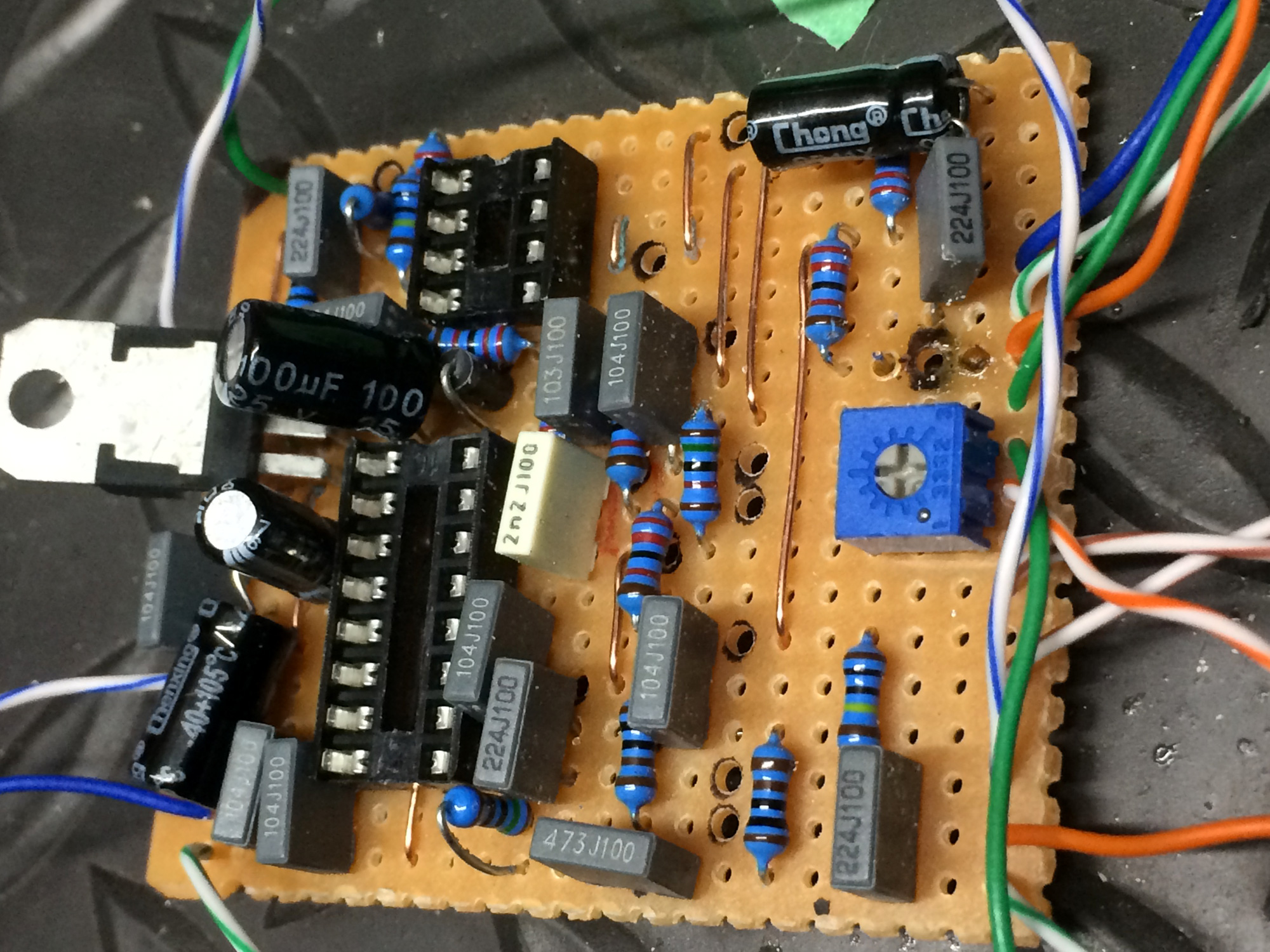
OK!! I built this, but am having some problems...
I put a 10 ohm resistor at the spot right after the 9V input, it immediately burnt up. Then I put a 10k resistor there instead of the 10 ohm, no burning, but also no signal. So, I took the 10k out and bridged the cut (bypassing any kind of resistor there) and i'm getting a rhythmic pulsing but still no signal. I have a jewelers saw that I use to cut all the traces, so I'm close to positive I don't have any solder bridges. Here is a photo of the populated board, if you can spot any errors, please let me know! (the 4001 diode has the white strip facing up). I also used a 7805 for the regulator instead of a 78L05, but that should not be a problem, and as far as pinout on that I looked it up and it "should" be in the correct orientation. Thanks! ![]() |
Free forum by Nabble | Edit this page |