Tape Echo Preamps
12
12
|
This post was updated on .
As many of you know, the Echoplex EP3 preamp has become legendary after it was adapted for stompbox use, and it has become one of thew most requested builds that I've gotten lately.
I have tinkered a bit with it, adapting some features from the Madbean Fatpants + some of my own, with very nice results. So I thought that it would be a good idea to share my version of it. 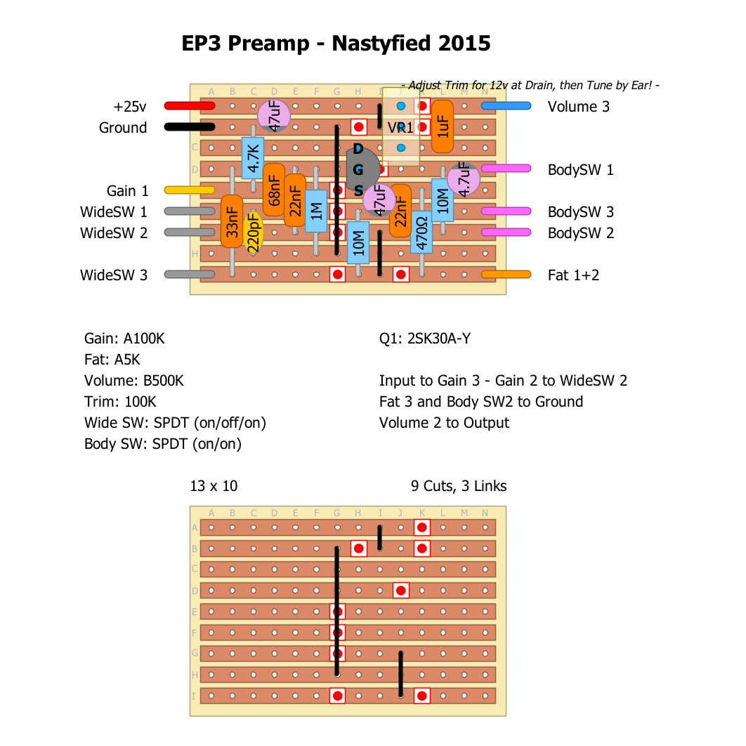 After building a couple and getting friends to try it out (with great success), a friend of mine said that the Echolette NG51 Tape Echo had his favorite preamp section. Way better than the EP3 he stated. This made me wonder if it was possible to adapt some more tape echo preamps for stompbox use, and I have now managed to adapt a couple of them... Here's the Echolette NG51 preamp section (verified): 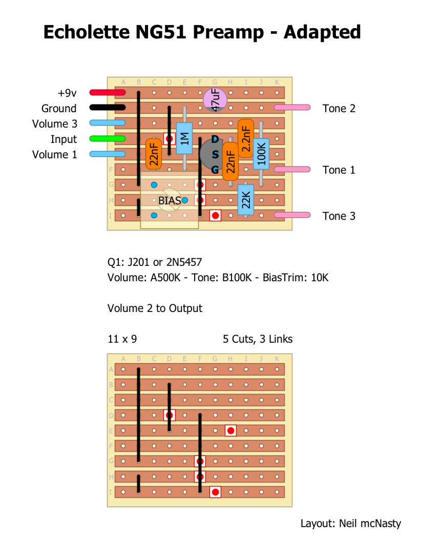 I recomend trying to run it at 18 volts as well. The only change I have done is in the tone-stack: The 22nf was 4.7nf in the original, so I increased it to match the input-cap, in order to get a wider range and more bottom end. (NOTICE: this one has issues with a bit low volume, and I will try to fix this and update when I find a solution) I also adapted the Roland SP201 (the Space Echo) preamp (there were some errors/cuts missing on the first one I posted, and I've renamed Volume into Gain and also added an Output Volume pot so that you can crank the input for some dirt with more control): 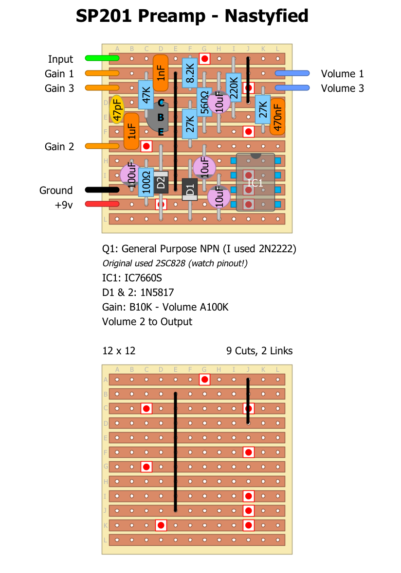 This one functions very well as a Preamp/Booster and has become one of my favorites. Enjoy this humble contribution... Cheers! |
|
It's good to see these veros, very good work mate. I really want to do the echolette... thank you!
|
|
Thanks a lot for these, Neil! I really like the SP201 preamp (running at 18V), and will build that one soon. Who knows - that may replace my Klon as my preamp of choice.

|
|
In reply to this post by Neil mcNasty
Awesome job on these!

check out my building blog at www.parasitstudio.se
|
|
This post was updated on .
In reply to this post by Neil mcNasty
The first Binson Echorec Preamp i uploaded turned out to be full of mistakes, even though it actually worked. Many of the mistakes were in the schematic I used, something I discovered after linking to the "cleaner" version of the schematic below. + the third transistor was not necessary, as it was part of the dry/wet merging stage.
I have therefore made two new ones: a 1 transistor version + a 2 transistor version, both with a charge-pump included. These should be a more correct adaptations of the circuit, and hopefully these are less noisy... 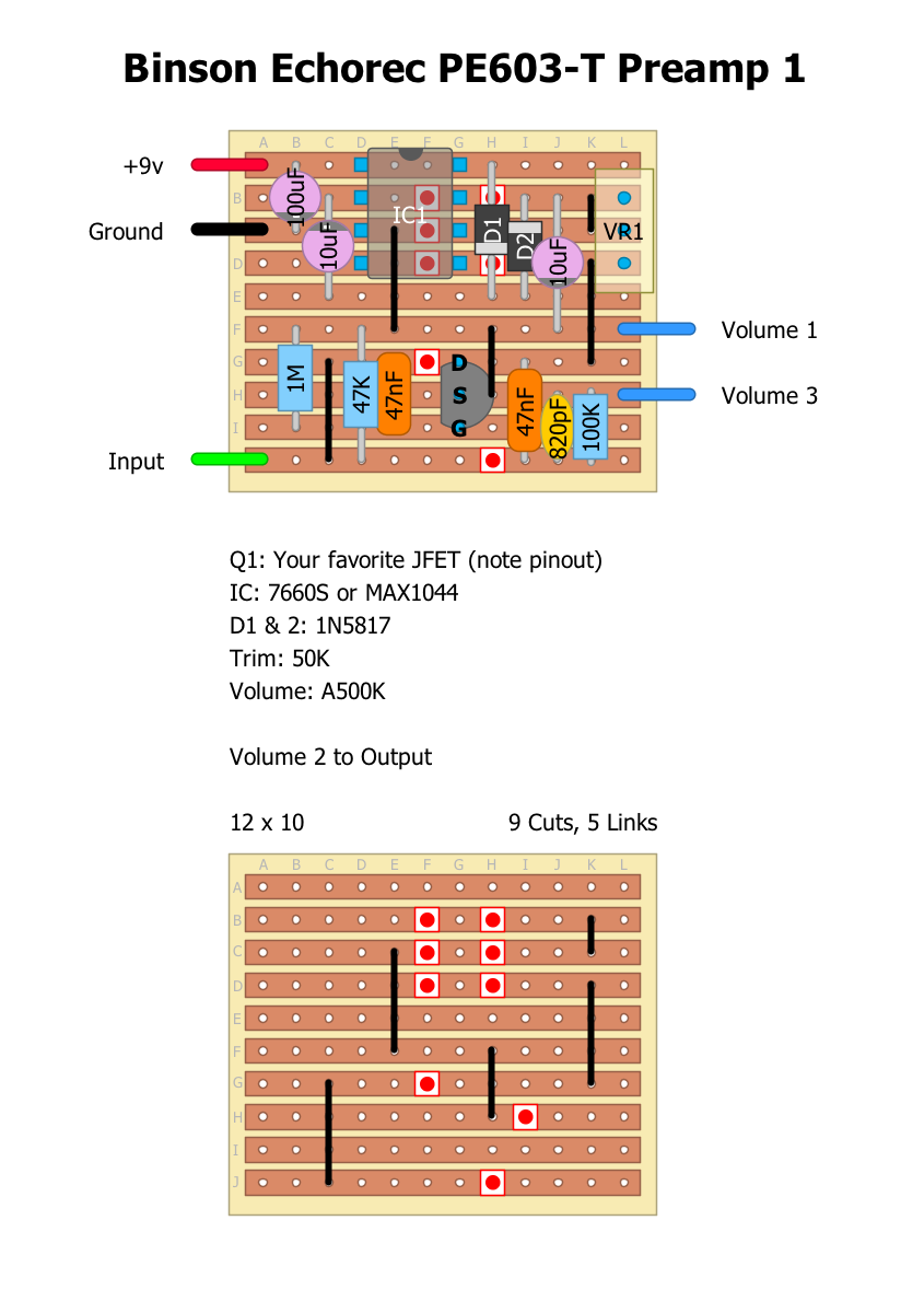 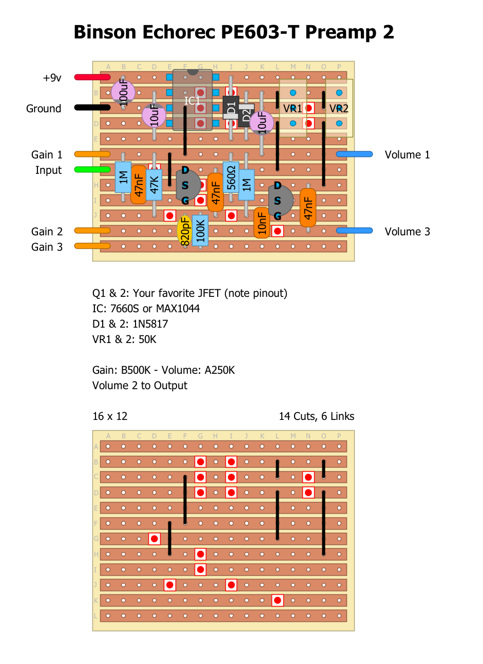 Here is a link to a schematic (pdf) |
|
Administrator
|
that looks awesome. the noise could be from the trimmers, and if you can set the voltage right, you could measure the resistance, and replace them with resistors and that could lower or remove the noise.
|
|
I wonder though, why did all those delays have preamps? Preamps that boosted and changed the sound.
|
|
This post was updated on .
I do not know why they all had preamps, but when looking at the EP3 preamp, I guess that some measures had to be done in order to make the tape technology sound good.
If you look at the EP3, you will notice that it rolls off quite a bit of the high end via the 220pf to ground at the input + filters away some of low end via the 22nf input cap. The result is a much more focused and gentle sound character that sounds very nice when boosted. My experience with the EP3, is that it makes all Delay and Reverb pedals sound much better, and pushes my amp into overdrive in a very tidy way. Also, when looking at the Space Echo, we can see a 1 transistor based instrument input preamp (the one I posted above), and then followed by a more complex 5 transistor circuit that is the "tape-amp", indicating that the signal probably needs to be boosted and shaped quite a bit in order to get a good signal on to the tape reel. After that you will also need a section that then "converts" it back to a more guitar amp friendly signal, since the output from the tape probably has too much gain and the wrong impedance. This is all guessing on my behalf, but that's how it looks to me with my limited humble knowledge on the subject. If you look at more "modern" delay pedals, they all have a buffer at the input, before splitting the signal, something i guess is the modern approach to this subject, as the shaping and filtering of the delay signal is done in/around the delay chip. I actually have a layout for the Tape-Preamp section from the Space Echo as well, but I have not built it yet. My guess is that it could have some pretty high output on tap and might be converted into an interesting booster, or maybe even capable of driving a small speaker... Give me a second, and I'll trow it in here, so that people can have a go at it . |
|
This post was updated on .
Here is the SP201 Rec Amp.
I have not built and verified it yet, and I have listed the most common used substitutes for the transistors, except for Q5, which I suspect is a low-gain transistor. There is an Inductor in parallel with a small cap at the output that I guess can safely be ignored. If doing so, move the Output to the top row... My possibility to build stuff is a bit reduced at the moment since I travel back and forth between home and Oslo (a 7 hour drive) where I have my workshop, and I'm almost out of resistors and hookup-wire at home... Therefore I am posting some of these layouts before verifying them. 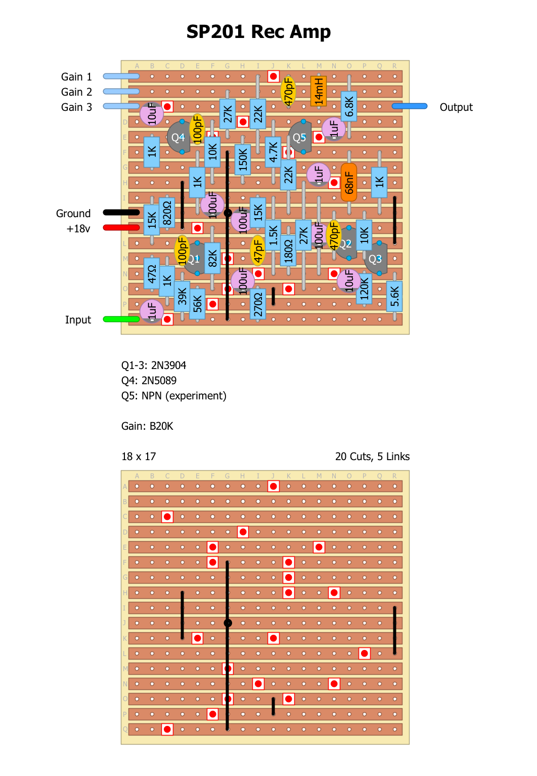
|
|
In reply to this post by Neil mcNasty
Hi Neil. I'm going to build the SP01 Preamp. Can I ask which diodes you used?
I've been using a SHO at the end of my chain, to give back some sparkle, cut some ugly bass frequencies and add a little grit. I'm hoping this will do the same but better (especially at 18v). In a pedal, I ultimately look for clarity that brings out subtleties in playing but adds character which brings an extra dimension of texture/harmonic. Thanks. Mark. |
|
Sorry! Forgot to add the diode info...
They are 1N5817 for the built in chargepump that feeds the circuit with 18v. (You can also use 1N4001, but it will give you a slightly lower voltage at the other side) Do not feed it 18v instead of 9v as in the layout! The chargepump allready does that internally, and the IC does not handle more than 12v when using the 7660s (9v maximum if using Max1044) Will update the layout as soon as I get back to my computer/confuser... I have totally fallen in love with the SP201 preamp, and it has now replaced my modified EP3. I have not tried to use it up-front as a booster in my pedalchain yet, but it works magic at the end, responding very nicely when pushed by boosters and fuzzes, giving a very focused and clear tone with a concise and defined attack + some grit and sparkle when driven hard. Hope you'll like it! |
|
Thanks for the info. I did realise that the pedal runs on 9v. I've been learning from this site for around 3 years and made about 20 different pedals for my band.
Our guitar pedalboard is split, with some pedals in the effects loop and the others in the front. I currently use a fatpants as the last pedal in the effects loop, to control the level and definition of the delay and modulation. I have tried many other pre's in its place and they haven't worked as well - so I am impressed with that pedal already. Then the SHO is last in the front end and this is where I hope the SP201 will work well. I'll let you know when I've built it! Thanks again. Mark. |
|
Hi Neil,
I have only just got around to building this but I'm a little confused. If you look at the SP201 Preamp - Nastyfied and compare the board with components and without, you will see that the cuts are shown in different places. GA is missing on the top board and JF on the top board is shown as JG on the bottom. Can you confirm there are 9 cuts and where they are placed please. Thanks. Mark. |
|
Sorry 'bout the delay...
Layout has been updated! The only thing missing/wrong, was one cut missing at the top row on the cuts'n links layoput... |
|
In reply to this post by Neil mcNasty
Neil, Thank you for your schematics !
I may be building the RE201 preamp soon, and let you know how it sounds. About the Echoplex, this one is the first one i see which is supposed to run at 25V (most are either 9V or 18V -or 9V in with a charge pump inside, making it running at 18V internally). May i ask why did you choose to go for +25V ? Is it for more headroom ? Would it work fine as well if fed with +18V ? |
|
By the way, what should we add to have an eq section similar to the RE201 Space Echo, and a "mic/instr" input volume switch ?
This is what i found about the eq section : http://www2.ece.rochester.edu/~zduan/teaching/ece472/projects/2016/Downing_Terjesen_paper.pdf "The tone control schematic, shown in [1], resembles a buffered Baxandall filter, which was first proposed in [5]. It employs user variable treble and bass controls via variableresistors. Altering the value of the treble control will slightly amplify or attenuate the bass re-sponse. Each potentiometer is independent from one another, but does not independently control the frequency response; instead they function as a network. The signal must is am-plified before and after the variable passive filter in order to preserve signal integrity by the BJT amplifier networks shown implemented by Q1 and Q2. The treble variable resistor net-work (R4 and R5) also employs positive feedback capacitor, and the network is tuned for a crossover frequency of 750Hz. Intuitively, this means the Treble control attenuates oramplifies frequencies above 750 Hz, while the Bass control(R6 and R7) attenuates or amplifies frequencies below 750Hz. " And the schematics here : http://invalid.ed.ntnu.no/~karlto/diy.html 
|
|
Hello,
I built the Echolette preamp today (thank you for he layout !). I have a couple remarks about the layout : - It seems that the transistor is in the wrong orientation. - I also think that the Tone 1 is on the incorrect trace line. It should be placed one row up on the 'E' track not the 'F' track. I built it using these two modifications and it works ok. Pusing the input harder make the circuit overdrive quite quickly, in a good way ;) However, like you mentionned, the volume is quite low (slightly below unity gain). Did anyone figure out a way to make it louder ? |
|
In reply to this post by Neil mcNasty
Hello, I will build the Echolette Preamp, but i would have a couple questions : 1- Did the volume issue got fixed? 2- Is it good to use with a bass (won't the 22nF input cap cut too much bass?)? 3- Do you know how much the input signal can be boosted ? Can we add an input gain ? Or put a booster afterwards? Thank you |
|
In reply to this post by Neil mcNasty
i tried building the sp201 preamp 3 times but no success.
wonder what am doing wrong |
|
finally got some sound by bridging CC.
now the gain pot doesn't work. the charge pump is giving off a high pitched whine, wonder if its because i'm using an 1044S? |
«
Return to Preamps
|
1 view|%1 views
| Free forum by Nabble | Edit this page |


