Top Gear Fuzz Sustain
12
12
|
Hi,
I have a 'Top Gear Fuzz Sustain' and wondered if I could take some pictures or whatever (I don't know how you guys do it, and don't know what it takes) so that you could clone it. The reason being is that it is pretty damn special - and unique in its sound (Half way between Fuzz & Overdrive) I have a million pedals, old and new - and this is the best that I have. And they are as rare as hens teeth, I can't find a video anywhere of the Fuzz Sustain, and the only time they come up for sale they are about half a grand or something. (I found mine on a bootsale for £2 and didn't know what it was) Anyway i think it should be shared, because nobody in their right mind should have to pay £500 for a pedal. But it is £500 special sonically. Anyone interested - just let me know Matt. |
|
Administrator
|
I'm interested! If you post high res photos of the top and bottom of the circuit we may figure it out
|
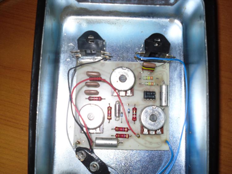 This is a View of the top of the Circuit, But alas, it is Glued rock solid into the case. If you know of a way of getting it out without damaging it, I don't mind trying. You can see the traces through the board from the top - I don't know if that helps (See image) And if it does I could take more photos so you can see everything. I assume it's hot glued to the box. I'll try my best with whatever you ask but I dont want to Knacker it, Like I say it is rock solid fixed, I have just pulled it so strong the board was bending, and it still didn't come away. |
|
Modified Dist+? You could try following this schematic with your multimeter and see if they match (or close).
As for removing..undo all nuts on the pots and try heating the board/enclosure with a hair dryer or heat gun. Hold the board at the sides and slowly turn it CW and CCW. Much less stress on the board than trying to peel it away. If it starts to move then it's working. If not then....... 
|
|
Administrator
|
In reply to this post by mattfode
Looking at the board it is probably some sort of modded Distortion + type circuit
Don't try and pull the board out by force. You need to take the knobs off and remove the nuts from the pots. That will free up the PCB which is mounted by the pots. You'll probably want to loosen the jacks too so that the board doesn't snag the wires to the jacks when you lift it |
|
In reply to this post by mattfode
Found this if it helps
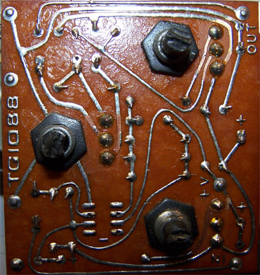
|
|
Administrator
|
I saw a clearer shot of the resistor values on fxdb too. I can't see many of the cap values though. The tropical fish look like they're all 100n, can't read the axials though. It looks like boost and volume pots are 10K and tone is 100K. Hard to tell though
|
|
In reply to this post by mattfode
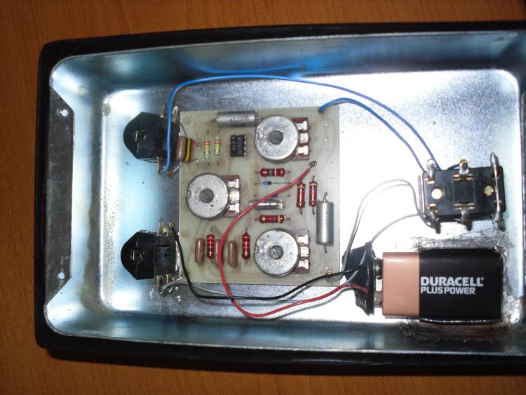 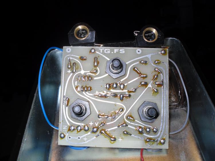 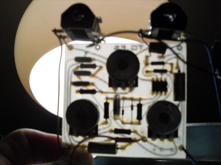 Volume & boost are 10k and tone is 100k The tropical fish are two types and have have the banding (from top) brown/black/yellow/black/red brown/black/orange/black/red the one on its own is: brown/black/yellow/black/red The row of three starting from the top by the jack input are: brown/black/yellow/black/red brown/black/orange/black/red brown/black/orange/black/red the two big silver caps - looks like it says 10uf I can look in depth with a magnifying glass if people are still interesed. Same goes for the chip - i cant see with naked eye I'll leave it in bits for now so I can try to get whatever info you require. Just ask and I'll do my best with my limited knowledge to get whatever you want |
|
Administrator
|
i'm on it. just printed the last pic you send and will draw up a schematic, then make a layout. keep an eye out on the main page for it. shouldn't take me too long.

|
|
Administrator
|
In reply to this post by mattfode
The tropical fish use the same color code as resistors, so the ones with the orange stripe are 10n while the ones with the yellow stripe are 100n. The IC looks like a 741 in other pics on the web
|
|
Administrator
|
alright. i've traced it, made a schematic, and a layout. i need some more info though before i post the layout. here's what i need to know:
1 - what's the taper of the pots 2 - what's the cap in series with the diodes 3 - what's the diodes, i'm assuming they're 1N914, but if you can see the number on them that would be awesome 4 - it's hard to make out the resistors 100%, so if you could list the values i can make any changes needed. otherwise it's kind of a crap shoot if they're right. btw, it's definitely not based on the dist+. the clipping arrangement is similar to a ts, but predates it, which is pretty interesting, and it's really an odd circuit. it seems rare that we come across something unique these days, so i can't wait to build this. so thanks for bring it up and providing the gut shots needed to trace it. 
|
|
Someone is selling one on reverb ( crazy Price) But it includes some way clearer photos than what I have provided and they may answer some of your questions. Have a look and let me know what you still need (see link) https://reverb.com/uk/item/2651189-1979-top-gear-fuzz-sustain-very-rare-top-gear-of-england-fuzz-pedal?_aid=pla&pla=1&gclid=CJv47_Oft84CFQu3GwodH30Dwg |
|
In reply to this post by rocket88
The vol says : Log B
The tone & boost Say Lin |
|
In reply to this post by rocket88
On the diodes i can make out (I think) On one (as written): 41 48 or it may be: 41 43 (If I had to bet it would be 4148) The other I think I can make out: 1T and then some other digit I cant make out which looks like a possible 1 |
|
the ic has the codes:
MC1741SCP1 M 705 |
|
Administrator
|
In reply to this post by mattfode
If I were to bet I'd say they are ITT 1N4148
|
|
Administrator
|
Aww.esome. I'll have the layout up in a few. It's interesting cause I found some clearer photos, which I used to trace it and there are a bunch of values that are different then the ones in this pedal. I really want it to match this one since you say it sounds real good. They may have done what ehx used to do and just use values they had that were close enough.
|
|
Administrator
|
ok, we're basically good to go. can't make out 2 parts.
1 - the cap that's parallel with the diodes. 2 - whats the 2 resistors on the left side of the board that are in line with the 3 caps. if you don't know what the value is the color code will be fine. i need to verify them, because in all the pics i've found they appear to be the same value, which makes 0 sense since they're in the tonestack. |
|
Both of the resistors that are nestled between the 3 tropical fish (If you mean these) are from left to right:
Gold/orange/orange/orange (33k) Th cap next to the diodes if thats what it is (It has a glass shell which I am not familiar with) I can make out these markings (as written): 1000 5% 160 Let me know if thats everything (I assume you have seen all of my other posts with the chip & pots etc details on and the link to a clearer photo on reverb) If you need me to get a meter to anything just let me know also. |
|
This post was updated on .
In reply to this post by rocket88
Hi Zach. I made this schematic a few days ago but was waiting for you to post first. Hope you don't mind my putting it here now. Your layout matches all the way up to the tone pot but differs in the output.
Schematic (hi res here) Now updated to include Zachs component values 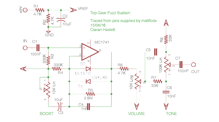 Reference pics Comp Side 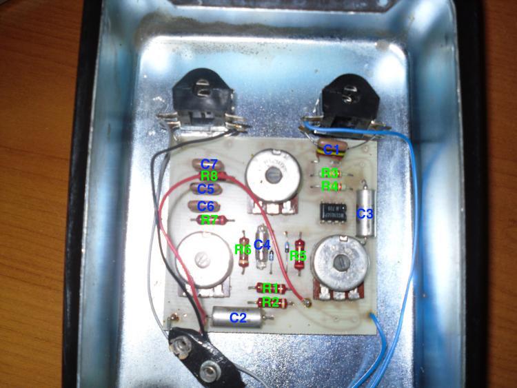 Trace side (flipped) 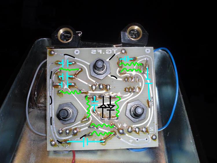 Compared to this...Tone 2 goes through a cap to OUT. Your layout currently has it connected to pin 5, and you have a cap connected to pin 6 where there shouldn't. Compare your schematic to mine and let me know what you think. Cheers |
«
Return to Open Chat
|
1 view|%1 views
| Free forum by Nabble | Edit this page |


