Wiring for Arctic White Fuzz

classic Classic list List threaded Threaded
63 messages Options
1234
Reply | Threaded
Open this post in threaded view
|

RE: Wiring for Arctic White Fuzz

rocket88
Administrator
Tayda is a company from Thailand, but they have a distribution center in the US in Colorado. So if you're in the US they ship out from there priority mail.

About the pot condoms, smallbear sells them, and so does Barry over at guitarpcb.com has similar ones in latex purple ones.
Reply | Threaded
Open this post in threaded view
|

RE: Wiring for Arctic White Fuzz

Ciaran Haslett
In reply to this post by falconfan
No problem lad.  Like I said...we all had to start somewhere.

Your build.....all looks great.  I think your problem may be coming from some confusion with the off board stuff.  When I first started out the whole grounding thing was an issue for me.  I was told by a site member (Rocket or lvlark I think ) that it doesn't matter how you connect the grounds together, as long as they are all connected together.

So for my personal builds I now solder a lead to each ground point in the pedal (circuit, DC jack, In/Out jack, switch) and bunch the other end of all these leads together and solder and insulate.  Much quicker than following lvlarks wiring in the off board section, but absolutely hoachin looking.  That means "horrible" in Ireland!

But hey....it's for me.  And I only care about how it sounds.  Believe me...you should see some of my "painted" enclosures

The confusion slowly disappears over time (much like learning your first barre chord).

Looking forward to hearing about your first successful build

Ciaran
Reply | Threaded
Open this post in threaded view
|

RE: Wiring for Arctic White Fuzz

falconfan


So I took a break from the dyna red and have went back to wiring the artic fuzz again. Got the vol, tone, and fuzz controls wired andnnow I needmsome direction with the LED, ground, and dc jack....just want to make sure im wiring everything right. Ive enclosed pics of everything done so far....also....dumb question....which is the ring on the input output jack

Reply | Threaded
Open this post in threaded view
|

RE: Wiring for Arctic White Fuzz

tabbycat
This post was updated on .
hey falconfan, this is the system i use.

http://guitar-fx-layouts.42897.x6.nabble.com/Newbie-question-tp22471p22487.html

there are others mentioned in this same thread so if the gaussmarkov doesn't suit you try another until you find one that fits.

offboard wiring is a real pita when you're new to it, so don't be too quickly put off. it's just one of those things. i used to find it harder than making the layout because at least on the layout everything is documented, whereas there is an element of having to research the offboard wiring for yourself when you first start.
definitely worth reading through a lot of this thread (one i linked to above) as it refers to another member who was in the same situation (we all have to go through it at some point).

also worth trying the search function here to look for keywords that relate to your difficulties. may save waiting for a member to pick up the threads if you are in a getting-on-with-things mood.

i hope this helps.

if it is any consolation, once you have really got into a good system you can remember for doing your offboard wiring, it will last you your entire pedal building career. so worth a bit of time and investment. it's the one things that you will definitely have to deal with in every build.

good luck with your build.

Reply | Threaded
Open this post in threaded view
|

RE: Wiring for Arctic White Fuzz

falconfan
Well, I went back and rewired the Arctic White Fuzz hoping I would have better luck and get it up and running. Well, I plugged it in and nothing again.....no power....no sound....nothing....here are the latest pics...please excuse the messy wiring...I'm still learning....lol


Going off the wiring diagram from this site, this is how I wired everything.
Lug1 - Connected to -LED (+Led to board)
Lug2 - Connected to Lug3
Lug3 - Connected to Lug6
Lug4 - Connected to Lug9
Lug5 - Connected to Fuzz 3
Lug6 - Connect to Output jack
Lug7 - Connected to Volume 2
Lug8 - Connected to Output Jack
Lug9 - Connected to Input Jack

Ground wire from board connected to dc jack
9V wire from board connected to dc jack (+)

Here is a bearfoot enclosure I found online.....and it's way different than mine and is different than the wiring diagram I was told to go by......thus my confusion on how this thing should be wired up...


Please forgive my lack of knowledge on this stuff...I'm trying my best to learn without bugging everyone....but I get a little frustrated with myself because it seems like it should be so simple. if anyone out there could help I would greatly appreciate it.

Reply | Threaded
Open this post in threaded view
|

RE: Wiring for Arctic White Fuzz

Ciaran Haslett
Right....forgive me if any of this sounds patronising.  Trust me it's not supposed to.

Lets start with the switch.  There's more than 1 way to skin a cat, as they say.  That wiring method is different than the one you used but thats irrelevant.  All of these are mechanical bypass wiring schemes, meaning there's a physical, metal touching metal, connection being made between all our wires.  So it doesn't matter what wiring method you use.  It only matters what connections are being made.

So can you confirm the following again (sorry)...
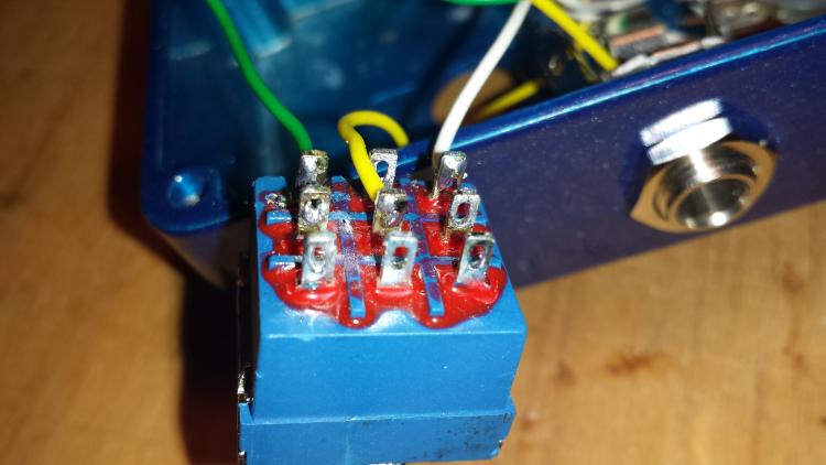
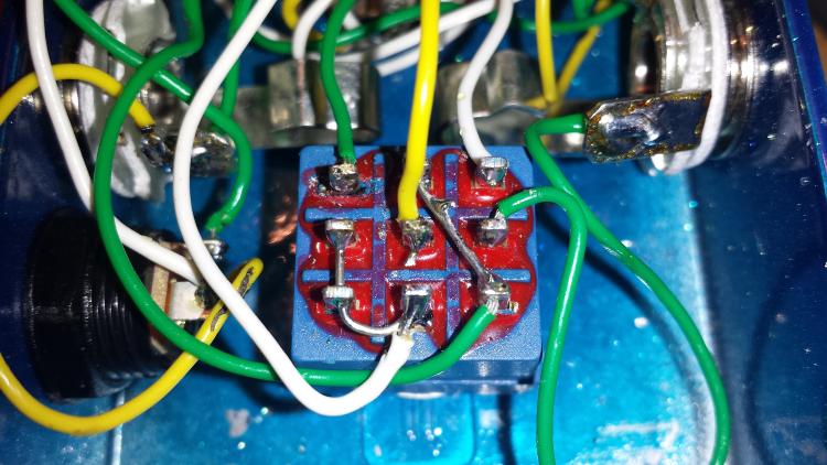
Lugs

1-4-7
2-5-8
3-6-9

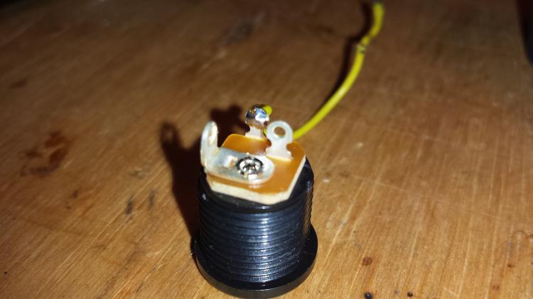
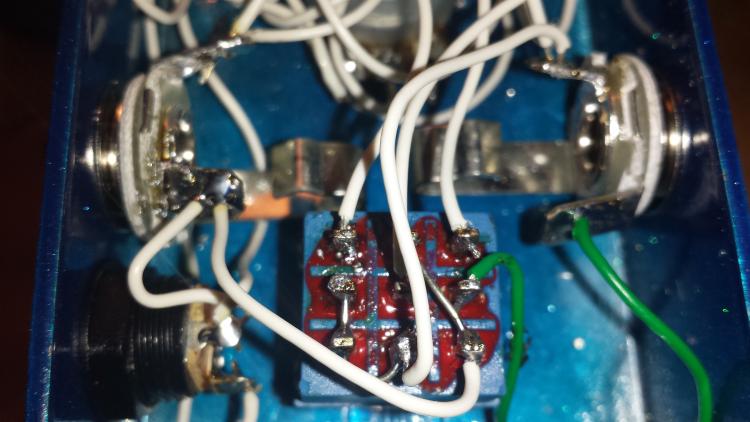
1. Connected to LED - (shorter leg, flat sided)
2. Linked to 3 and 6
3. Linked to 2 and 6
4. Linked to 9
5. Circuit Input on board
6. Ground (any of them)
7. Output from Board (Volume 2 in this case)
8. Output Jack Tip (the lug sandwiched between the round disks)
9. Input Jack Tip (the lug sandwiched between the round disks)

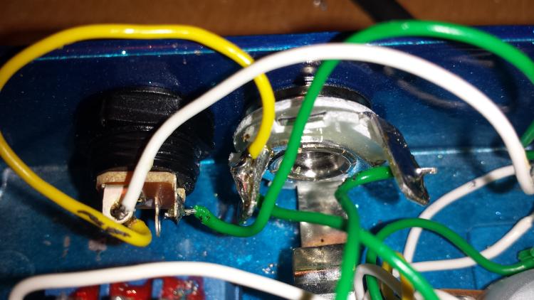
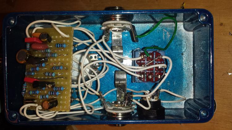
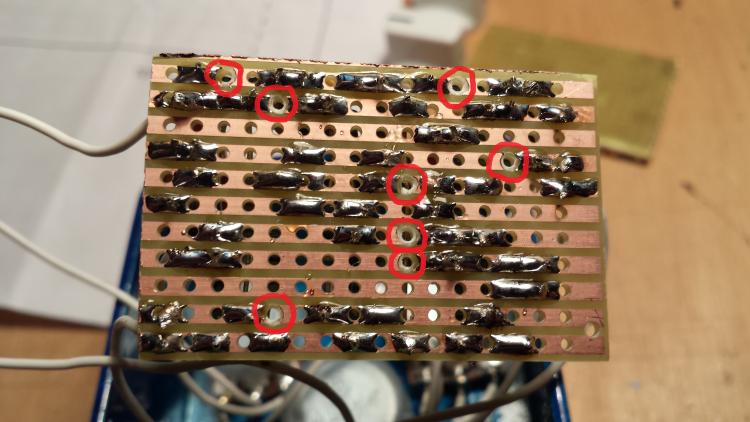
Can you confirm that EVERY GROUND POINT is somehow connected to each other.  By this I mean...

Input Jack ground lug connected to Output jack ground lug AND connected to the DC jack ground lug (the square one) AND connected to the switch on lugs 2, 3 or 6 AND to the board ground wire.

As you can see, every ground point MUST be connected to each other physically.  Any one of these missing will result in either a loud hum or no sound at all.

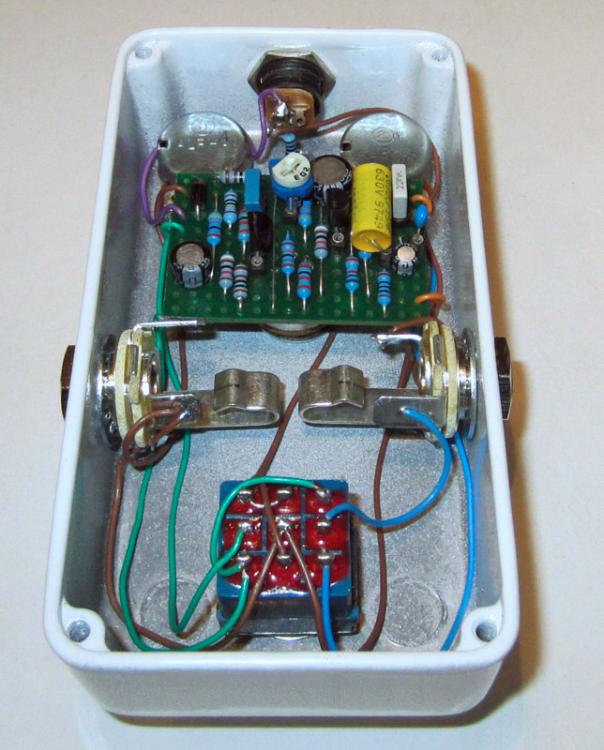
Now, if all the above is confirmed to be correct then you should at least get you unaffected, clean bypass signal.  No power is needed for this as the connections are not related to electronics (hence the term True Bypass)

Looking at your switch, where is that white wire coming from on lug 6?  That should also be going to a ground point as its sole purpose is to ground the bottom lugs so that the switch will complete a circuit allowing the LED to light up AND to ground the circuit input when you turn the effect off (prevent noise)

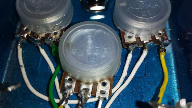
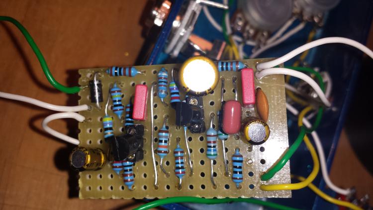
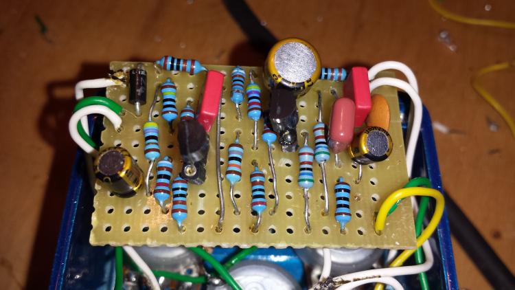
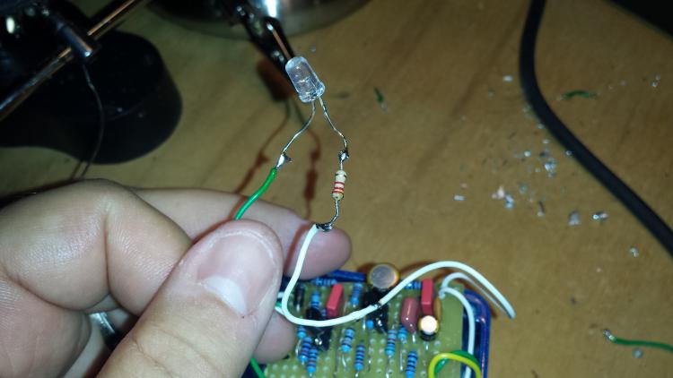
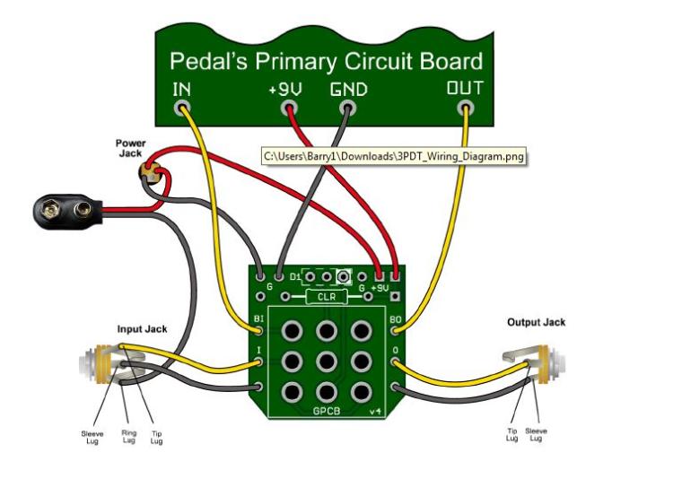
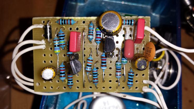
And your LED....if you look at the layout, it has an LED + wire.  Beside that wire is a 1K resistor and the other side of that is another 1K > diode > 9V.  So this LED already has a current limiting resistor.  You can remove the one you soldered onto its leg.  The more resistance, the dimmer the LED.

Can you confirm all the above?  I appreciate how frustrating all this is when starting out.  There's a lot on key concepts here that are most likely the first time you've ever come across them.  But they're key concepts none the less.

And apologies again if any of this comes off as grandiose.  If we start from the very bottom we can identify any misunderstandings that the more experienced builders might overlook.

Good luck

Ciaran
Reply | Threaded
Open this post in threaded view
|

RE: Wiring for Arctic White Fuzz

falconfan
Ciaran,

Thanks so much for your response.....I see that anything you say to me is a benefit because I've learned alot from you already.....so it's not patronizing to me....sometimes the most obvious things take time to see....

I've checked the following:

Lug 1 - connected to the flat side of the LED - checked
Lug 2 - Linked to 3 and 6 - checked
Lug 3 - Linked to 2 and 6 - checked
Lug 4 - Linked to 9 - checked
Lug 5 - Linked to Fuzz knob lug 3 - checked
Lug 6 - linked to output jack (the negative sleeve) - checked
Lug 7 - linked to volume 2 -checked
Lug 8 - Output jack Tip - checked
Lug 9 - Input jack tip - checked

I checked the ground wire from the board - it's connected to the dc jack (square tip) then I have another wire coming from the dc jack to the input jack (negative tip) then I have a wire going from the negative tip to the negative tip of the output jack, and then a wire coming from output jack tip to lug 6 on the switch...I know this is kind of backwards how I detailed it out...the one thing I noticed is that the wires are not connected together, I just have each wire linked to the locations. what I mean is, for example, the ground wire coming from the board is connected to the dc jack hole, but the next wire coming from the dc jack to the input jack doesn't touch the wire coming from the board. I just didn't know if you meant these wires had to touch each other in the same connection.

THis may be one of the areas I'm messed up on....

the white wire coming out of lug 6 is going straight to the output jack (negative tip)
Reply | Threaded
Open this post in threaded view
|

RE: Wiring for Arctic White Fuzz

Ciaran Haslett
I think we're getting closer...

You said you have a wire going from Log 6 on the switch to the output jack tip?

Output jack tip (the one sandwiched between the white disks) should ONLY go to lug 8 on the switch.  That way, when in bypass, lug 8 (Output tip) will be connected to lug 9 (input tip) therefore, true bypass

The wires them selves don't need to be connected together.  But as long as there's a PHYSICAL connection (for example Input ground lug to switch 6 to output ground lug....a physical pathway that electrons can travel...so both input and output grounds are still connected together)

Check that this is the case.

Is the LED lighting up when you press the switch?  Are you getting your unaffected bypass signal? (probably not based on what you just said)

We're getting there!!
Reply | Threaded
Open this post in threaded view
|

RE: Wiring for Arctic White Fuzz

falconfan
This is really weird.....so I took the wire off of lug 6 that was connected to the negative tip of the output jack....I went and plugged the pedal up and the LED started flickering.....so I moved the wires around and the LED came on...but I noticed the lug 1 on the switch was loose.....must have gotten too hot when soldering and loosened up the plastic....I also turned the volume and tone knobs while plugged up and noticed the hiss changed volume (low volume) and the tone changed.....so I unplugged and came backmto change the switch out....rewired a new switch and wired everything like I had it and now back to square one....no sound ( before imhad a hiss)...and LED doesnt light up.....

I feel im so close....lol
Reply | Threaded
Open this post in threaded view
|

RE: Wiring for Arctic White Fuzz

falconfan
So...just on a hunch....I wired up lug 6 to the output jack (like I had before) plugged up the pedal....LED came on....but there was a short somewhere...so I played with the wires and all of a sudden I got sound...loud and fuzzy....man alive I thought...finally got it...but then everything shut off and nothing...no LED and no sound....

I guess back to the drawing board tomorrow.....but with your help Ciaran....ive made progress....I can almost feel it about to come together....lol
Reply | Threaded
Open this post in threaded view
|

RE: Wiring for Arctic White Fuzz

rocket88
Administrator
Reply | Threaded
Open this post in threaded view
|

RE: Wiring for Arctic White Fuzz

tabbycat
In reply to this post by falconfan
i don't think you've posted a view of the reverse side of this board yet.

next time you have it out of the box (if the offboard wiring isn't the thing) it would be worth double checking that your cuts under the board properly match the layout. mark on the top of the board with a felt tip (or sharpie if your are in the states) all the points shown on the layout, then flip the board and you should be able to see the colour through the hole.


or just poke a bit of wire through at the cut points indicated (as viewed from above in this compound image) and then flip it and the wires should be going through the cuts.
though there are not many cuts on this one, because you are working in revers when you flip it to cut the tracks, it's quite easy to miss a hole.

from the sound of it (as rocket said) it may also be a badly connected wire. worth double checking that all your board to offboard connections (jack, 3pdt, led, etc) are good. sometimes when you solder too hot, or you don't strip enough plastic shielding away from the wire, the plastic and solder can sort of blend together to give a black crusty mess. which may hold the two things you are soldering together physically, but isn't a reliable electrical connection. worth considering.
Reply | Threaded
Open this post in threaded view
|

RE: Wiring for Arctic White Fuzz

Ciaran Haslett
In reply to this post by falconfan
Great.  As the lads said, it now deffs sounds like a poor wire connection.  Try reflowing all the wires on the board (melt the solder and add more if needs be).  I've had the same issue as Tabby described once or twice....the connection felt solid but it was actually the insulation had melted and bonded to the track, not the wire itself.

As for the switch lug 1.  My experience is that these switches can take only so much abuse with a soldering iron before the epoxy melts and dislodges a lug.  In some cases this shift the lug to the point where the rocker inside doesn't touch it anymore. (No physical connection).  That could also explain your LED problem but is sounds more like the wiring connections are the issue.

You can test all of this by just using you multimeter.  Set it to Continuity check and place one probe on the track where you've soldered a wire, and the other probe to the other end of that wire.  If it beeps then its properly connected.  If not then......

The switch works by rocking contacts, connected to the middle lugs, either up or down.  So in 1 position...lug 2 will connect to 1, lug 5 to 4, lug 8 to 7.....and the other position...lug 2 to 3, lug 5 to 6 and lug 8 to 9...like this

Position 1                 Position 2

1  4  7                      1  4  7
|  |   |
2  5  8                      2  5  8
                               |   |   |
3  6  9                      3  6  9

So probe the centre lugs to the top then bottom lug and check for continuity. Also bear in mind that you've make some more connections on the switch with the links.

Anyway....you're nearly there!
Reply | Threaded
Open this post in threaded view
|

RE: Wiring for Arctic White Fuzz

falconfan
OK everyone....so I got to looking at my pedal and decided to clean up the wiring....so I'm going back to rewire everything point of contact. I will let you know if I have better luck once it is done.

Thanks for everyone's help this week.
Reply | Threaded
Open this post in threaded view
|

RE: Wiring for Arctic White Fuzz

falconfan
Ok.....so I re-wired everything....and made everything a little neater......plugged up and all I get is a pulsing sound.....no sound from the pedal as far as effects.....just a loud pulsating sound through the speakers....

Any thoughts on where I went wrong?


Reply | Threaded
Open this post in threaded view
|

RE: Wiring for Arctic White Fuzz

rocket88
Administrator
Well I think I see the problem. It looks to me that you have the input jack and dc jack messed up. It could be the angle, but it looks like you have the output jack tip wired the the positive of the the dc jack. It's hard for me to see it clearly. The "L" on the dc jack is for ground.
Reply | Threaded
Open this post in threaded view
|

RE: Wiring for Arctic White Fuzz

falconfan
Hello everyone.........I've had success with my first full functioning build the Dyna Red Distortion (Thanks to Frank NH) and now I wanted to go back and tackle my first project I started on - the Arctic White Fuzz.

So, last night I rebuild the board and wire everything up, but I'm still having no luck getting any sound. When I touch the board while plugged up, its getting power, but no sound whatsoever. This is the 3rd time I rebuilt this board.

I am using the diagram below and also the 3pdt swtich board as shown. I've double checked my cuts and they are correct.

Could someone out there help me with this one again? I know I've come to this board before and you guys have given me some great input and I've learned so much since the first post. I just want to get this pedal working so I can move on to better things.


Reply | Threaded
Open this post in threaded view
|

RE: Wiring for Arctic White Fuzz

Ciaran Haslett
HI Falcon

Congratz on the Dyna

I've just re-read the thread.  I noticed you said that one of the switch lugs were wobbly.  Are you using the same switch now?

I'm sure you're now familiar with how we all tend to operate here.  We like to test the board first before we wire it up to the footswitch and jacks.  This confirms that the board works BEFORE we start wiring up.  If the completed build doesn't work when we finish boxing, the most likely problem is a wiring issue.  Narrows down the list of suspects.

Thats too late for you now but you can still bypass the switch.  

Wire the board input right to the input jack lug (sandwiched between the wafers) and the Volume 2 wire right to the output jack.
Connect the board ground to the input and output jack ground lugs (the centre ring) and to the DC ground lug (the square one)

If it's wired correctly as above and still no sound the the problem is on the board somewhere.
If it's wired correctly as above and it works the the problem is the switch

Report back

Can we get some clear pics of the offboard wiring too?

And is everything OK with that transistor.  Looks like the top leg isn't in its socket.
Reply | Threaded
Open this post in threaded view
|

RE: Wiring for Arctic White Fuzz

falconfan
Good to hear from you Ciaran,

I have changed out the old switch for a new one and soldered a switch wiring board to it for an easier soldering job on the switch.

I still have not truly learned how to use my meter to check the board (which I know I need to learn cause this is an important step). I just don't know exactly how to use my meter machine to set it to the right voltage and how exactly I'm supposed to check the board. I'm such a newbie....lol In the future I would like to check the boards before wiring.

I will get better pics of the offboard wiring tonight and report back.

Reply | Threaded
Open this post in threaded view
|

RE: Wiring for Arctic White Fuzz

falconfan
In reply to this post by Ciaran Haslett
Which transistor were you talking about Ciaran?
1234