BJFE BlueBerry OD Creation - Circuit Help
12345


12345
|
"i've decided that i have to make time to build something otherwise i'm going to lose my sanity"
You know, that's one thing I've discovered about this hobby. It IS very relaxing. When I start a build, I set things up in my work space, put on some classical music (YES, classical - I can think better  ) and solder the night away. Sometimes, I even drink a beer while building... ) and solder the night away. Sometimes, I even drink a beer while building...
|
|
Administrator
|
haha. oh i have a beer, or two, and as you know sometimes a lot more
 , which leads to some interesting end results. funny enough i usually put on psych rock, doom metal, or just heavy blues like clutch. everyone is giving me grief because i refuse to pack my parts for building, instruments, and amps. i've been reduced to having things stashing in a corner in boxes , which leads to some interesting end results. funny enough i usually put on psych rock, doom metal, or just heavy blues like clutch. everyone is giving me grief because i refuse to pack my parts for building, instruments, and amps. i've been reduced to having things stashing in a corner in boxes
 if you look directly at the corner those boxes have my resistors, Si transistors/JFETS/MOSFETS, clipping diodes, greenies, electrolytics (axial and radial), ceramics, multilayer ceramics, and poly caps. the one on it's side by the Army of Darkness (one of my favorite movies) poster is filled with all my Panasonic Poly caps 1nF-1uF. the standing drawers have all my pots, switches, leds, led holders, knobies, jacks, the cardboard boxes have 10-15 enclosures that i pre-painted, there are another 20-30 enclosures unpainted under my dresser, i have 15 painted enclosures for pedals i have to build for people in one of the cardboard box. those plastic shoe boxes are filled with Ge's, and those long skinny red boxes are NOS sfd-112's that just showed up. but i'll be damned if i pack it before the day before i leave. i'm deciding what i'm going to build. i'm thinking a DAM Ezekiel. seems to be a pretty good bass od/distortion/fuzz from what i've read, and i mean i am a bass player  lol. lol.
i also got to get this on the breadboard and mess around with it to figure out the BBBOD.... rant over.......see my mind is gone.......i need to build something 
|
Re: BJFE BlueBerry OD Creation - Circuit Help
|
Alright I tried some modeling, my program is being an asshole but I will tell you that the original BB probably doesn't have the 47K/4n7 parallel network thing at the end. I'll try breadboarding it, it's seriously easier. Fucking SPICE...
Through all the worry and pain we move on
|
|
Administrator
|
i've started putting it on my breadboard too, not done with it yet though. i wonder what the reason for that 47k/4.7nF parallel network is. i'm still thinking the biggest changes we have to make will be ti raise the input cap to something higher then 47nF, if we lose the 47k/4.7nF parallel network, then there's a 1uF output cap which should be more then enough for bass, and tweaking the filters, not sure if the "nature" control is fine, but the filters there may need some tweaking too. but i think the breadboard will be the best way to figure this all out.
shame there's no way to put the circuit together virtually and be able to test it, and play with the values, sort of a virtual breadboard. if something like that existed can you think of the possibilities for DIY pedal building? |
Re: BJFE BlueBerry OD Creation - Circuit Help
|
OMG that would be amazing. If it was SPICE-based though it would be tough to factor in the variance in parts that happens in real life I suppose. Different chips and FETs and so on have subtle effects on the tone that I'm not totally sure a 100% virtual modeling system could replicate.
But yeah Multisim is designed for prototyping integrated circuits, and it sure does have its uses (I've done a lot of active and passive filter tweaking with it) but for some reason it doesn't do much with entire stompbox circuits. It also doesn't like clipping diodes (reads them as an error... infuriating). And the HB/BB have much more complex filtering going on than just a passive network or a feedback-loop active EQ, that need parts from across the circuit to function correctly. There isn't really a place I can isolate that filter network after the 3130, for example, because it loops back to the inverting input of the op-amp. What shows up if I try to model the whole circuit is a curve implying a -130dB cut in volume and an enormous bass roll-off, which is obviously extremely wrong  perhaps it's something I'm doing wrong, I have no idea. perhaps it's something I'm doing wrong, I have no idea.
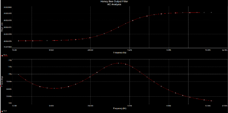
But yeah the RC network at the end there does this:  (Don't know if you can see that, sorry for the crude screen capture. Top is frequency response and bottom is phase, with a 1kHz input) which doesn't seem to be very good for bass. (Ignore the dB, I fed the thing with 10v p-p.) I'm just thinking the final product will have a gain structure like the HB but filters tuned somewhat like the MP.
Through all the worry and pain we move on
|
|
Administrator
|
Hmmm. That's interesting. So that parallel cap/resistor is acting as a frequency cut, if I'm reading the graph right. So....I wonder what happens if we just drop if from the circuit, and raise the input cap if that would be the solution.
I completely agree that a virtual breadboard couldn't capture all the subtleties in different IC's and manufacturers, but if there was something out there that could at least give an idea about what you would expect, then spend time building if on a real breadboard where you can explore the subtle differences. If thF makes sense. |
Re: BJFE BlueBerry OD Creation - Circuit Help
|
Yeah sure does. That would be awesome.
Yes you are right, that bass cut isn't good at all. Now regarding the input high-pass, the 47n/1M filter has a corner frequency of 3.4Hz, which should be plenty low for bass. Try this set of mods (starting from the MP schem) and see how it works: 1. Remove the entire first gain stage. Input should be as the HB. 2. Gain pot 500K, minimum gain resistor 2K 3. Nature cap values somewhere between the two versions - this is what we need to find out. 4. Leave the major filter block as is. 5. Recovery stage is 5457 without the base voltage divider, with MP resistor values. 6. 1-10uF output coupling cap 7. No parallel network at the end there. Values for the power section in the HB seem a little arbitrary - 31K6 for the Vref divider seems a little overly specific when the only requirement is that both resistors be the same value. 10K is most commonly seen, the MP uses 47K, I don't think it really matters. I also doubt there's much difference in that the CLRs are 4Ω apart. Let's see how it goes...
Through all the worry and pain we move on
|
|
Administrator
|
This post was updated on .
i took some time to draw up a quick schematic based on the ideas you came up with. so if' i'm correct in my understanding it should essentially look like this.
|
Re: BJFE BlueBerry OD Creation - Circuit Help
|
Yeah looks about right, except you forgot the 1M to ground on the gate of Q1. HB has just that while the MP has a 10M/1M voltage divider, I meant just keep the 1M. Also R11 might be something you'd like to play with, MP has it but HB doesn't. Original could be either or neither.
Through all the worry and pain we move on
|
|
Administrator
|
ahh, ok. Fixed
i was also thinking that we need a way to lower the gain, since the original was more low - medium gain, where as the MP has much more gain on tap. |
Re: BJFE BlueBerry OD Creation - Circuit Help
|
This post was updated on .
Well there's a few ways you could do that. You could either drop the value of the gain pot or raise the value of the low-pass resistor (that would be R10). In general terms, the gain of a non-inverting op-amp stage is 1 + R1 (feedback loop resistor)/R2 (outside loop/low-pass resistor through cap to ground). So Av = 1 + Drive/R10 (made specific to this circuit). If you go the latter route you will almost certainly need to adjust the values of C7, C8 or both to preserve the frequency response (since R10 is also part of the low-pass filter with C7 and potentially C8). Just as a point of interest, this is why the MXR Distortion+ is shit for bass - they decided to control the gain of the stage by making R2 (=R10) the variable resistor, so as you vary the gain the corner frequency of the filter changes as well, cutting the bass out at low gain settings. Moving the pot to R1 removes this odd and undesirable characteristic. I digress, if there's a gain problem it'll almost certainly be in the op-amp stage. You could also play with the resistors around the recovery stage, but that'll probably mean testing individual FETs for optimal operating point. Just going by ROGs approximations the gain will probably be (Rd*Rs)/2 for midpoint bias or if you use the Fetzer Valve biasing technique (maybe could work since there's no bypass cap of a traditional definition on Q1) it'll be 0.54*(Vcc/|Vp| - 2.). I don't foresee that part needing much tweaking but you never know with Bjorn's black magic
 . .
EDIT I always forget the stupid 1+ in the gain equation. Gah lol
Through all the worry and pain we move on
|
|
Administrator
|
 doh, i always forget that by altering the value of the drive pot in a circuit like this would raise or lower by raising or lowering the resistance of the gain pot. i'll be able to get it on the breadboard friday after work, before i enter the badlands with my buddies. maybe i'll get lucky and get some time and get it together tomorrow. hopefully you'll be able to get some time to breadboard it too, and we can continue making headway on this. 
|
|
Administrator
|
This post was updated on .
well, i started to put it on my breadboard and i keep making everything get too squashed and i run out of space. for whatever reason i just have issues building IC circuits on my breadboard, and don't get why, so silver i'm leaving it up to you to get it on the breadboard. i'm going to make a layout for it as we have it on the schematic and put it together making the questionable parts sockets so i can swap out values to see what happens.
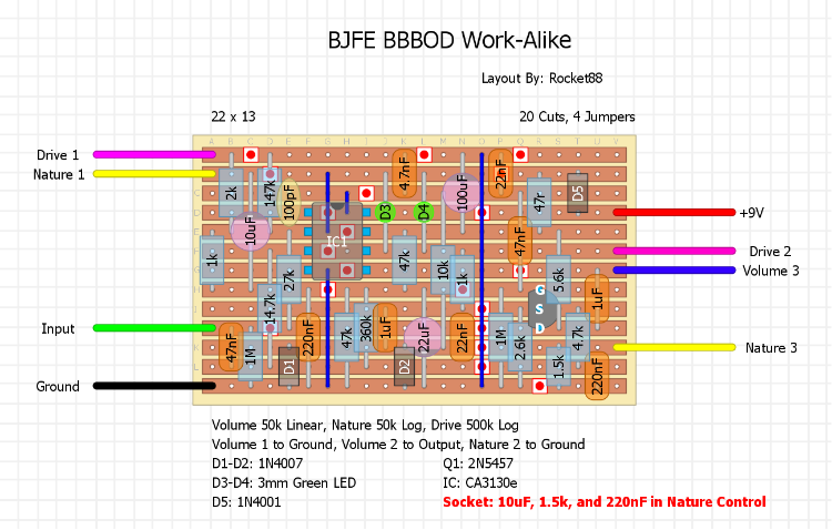
Unverified Layout Posted below based on the schematic above. If anyone wants to give it a shot, would be great to get more people working on this one.  btw, it's based on the layout for the bearfoot honeybee with corrections to values and change to the nature control to mirror the MP BBOD, so it should fire right up. |
Re: BJFE BlueBerry OD Creation - Circuit Help
|
Sure man, no problem. All I've got to do is find some jacks... I need to start buying jacks in bulk. They're the thing I never have.

Through all the worry and pain we move on
|
|
Administrator
|
i i think i just need to practice doing a small IC circuit first before i try something more complicated like this.
 i was able to get the hang of it with transistor based circuits, mostly because i was able spread everything out nice and easy, and with the IC i noticed everything was getting scrunched up and i was running out of real estate pretty quickly. i got to get the hang of doing IC's too cause breadboarding is super important and helpful, and there are a bunch of IC based circuits i'm looking at doing and modding.  hopefully between you breadboarding it, and me trying the layout i'm fairly confident we're going to finally crack this.. 
|
Re: BJFE BlueBerry OD Creation - Circuit Help
|
Indeed

Oh, now that I notice it, do we know the color of the LEDs? I assumed they were yellow but you have greens on your layout, and there's a chance they could be red. Knowing that would probably help too.
Through all the worry and pain we move on
|
|
Administrator
|
as far as i know they're green, like the honeybee and MP BBOD, but i mean we can experiment with different colors and see what sounds best. it's not like we really know what the circuit really looks like.
|
Re: BJFE BlueBerry OD Creation - Circuit Help
|
True enough. Alright cool
Through all the worry and pain we move on
|
|
Administrator
|
This post was updated on .
i have some good news!!!!!
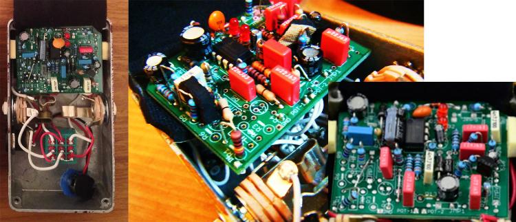
lohstah, over at FSB has a comparison pic of the Bearfoot BBBOD with that of the Honeybee, and guess what???? The board is the same, but some of the values have been changed. so now we have even more to go on to help us out get this working. one interesting note is that supposidely the honeybee uses green LED's, but apparently in the board that was photoed they're red...... btw, the board on the left is the BBBOD, and the right is the honeybee. it's really hard to make out a bunch of the values, but we might be able to see what we need or at least most of what we need to help us out more.  btw, here's a link to the post at FSB, where a larger image can be seen and DL. |
|
Are those standing resistors on the PCB???
 RE: LEDs I got one of those grab bags of LEDs at Radio Shack with 3mm and 5mm diffused and all different colors. Interestingly, they all measured to be about the same forward voltage (1.6 - 1.7 V), regardless of color. So when specifying LEDs, it would be nice to write down the forward voltage rather than simply the color. Don't know if you can test LEDs in circuit... |
«
Return to Open Chat
|
1 view|%1 views
| Free forum by Nabble | Edit this page |

