BJFE BlueBerry OD Creation - Circuit Help
12345


12345
|
Administrator
|
Interesting. I know that the water clear LEDs I have are different forward voltages, so I wonder if the reason the diffused are the same is becUse the internal led is all the same and the color is caused by the color of the plastic. But I totally agree that having the actual forward voltages for the LEDs and other clipping diodes. Unfortunitely, I have no access to the pedal to get readings.

|
Re: BJFE BlueBerry OD Creation - Circuit Help
|
That's fantastic! Although those pictures are really hard to make anything out from. All I can really see is that the red one is 22n and the two white ones are 220n. I think (maybe) that the grey one is 27n. I can't even really make out the colors on the resistors. It's anyone's guess what the blue film caps are.
But we know the LEDs are red! That's something! 
Through all the worry and pain we move on
|
|
Administrator
|
haha. did you get the pic from the link to the FSB thread? cause it can be enlarged and i can sorta make out a bunch of the resistors. but, yea we got the LED's down.

|
Re: BJFE BlueBerry OD Creation - Circuit Help
|
Yeah I looked at the larger picture, still couldn't make out much lol. I can see the bands on the resistors but I can't distinguish the colors is what the problem is.
Through all the worry and pain we move on
|
|
This post was updated on .
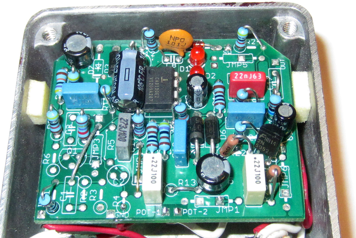
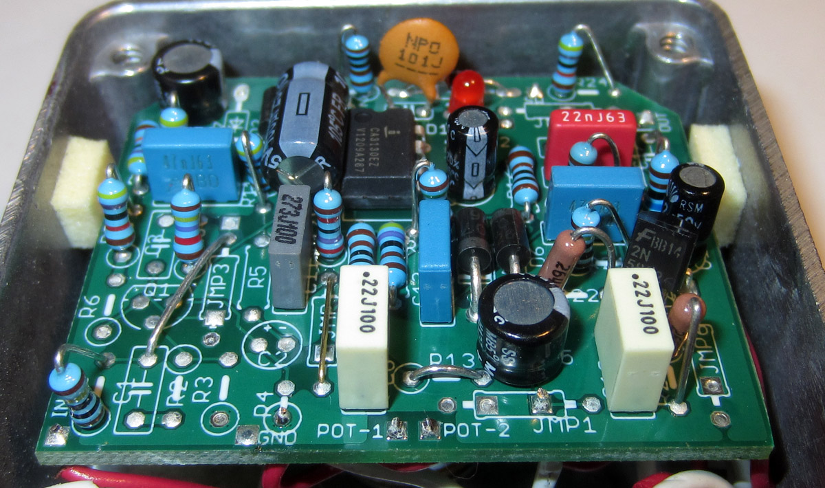
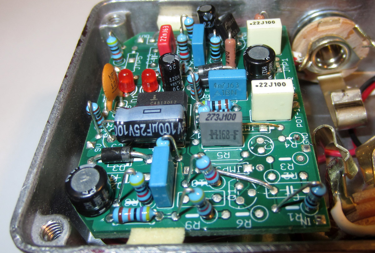
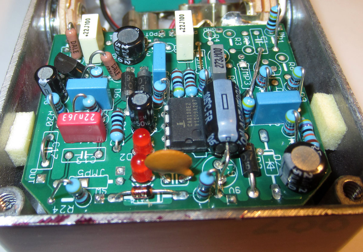
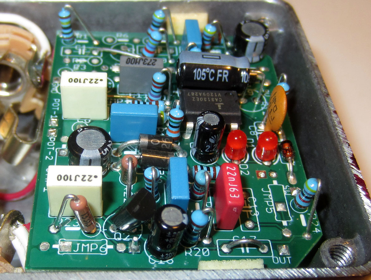
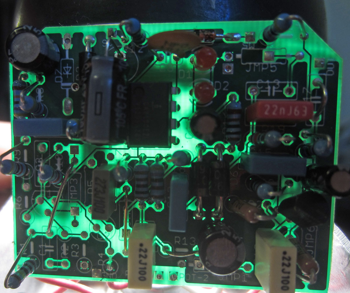
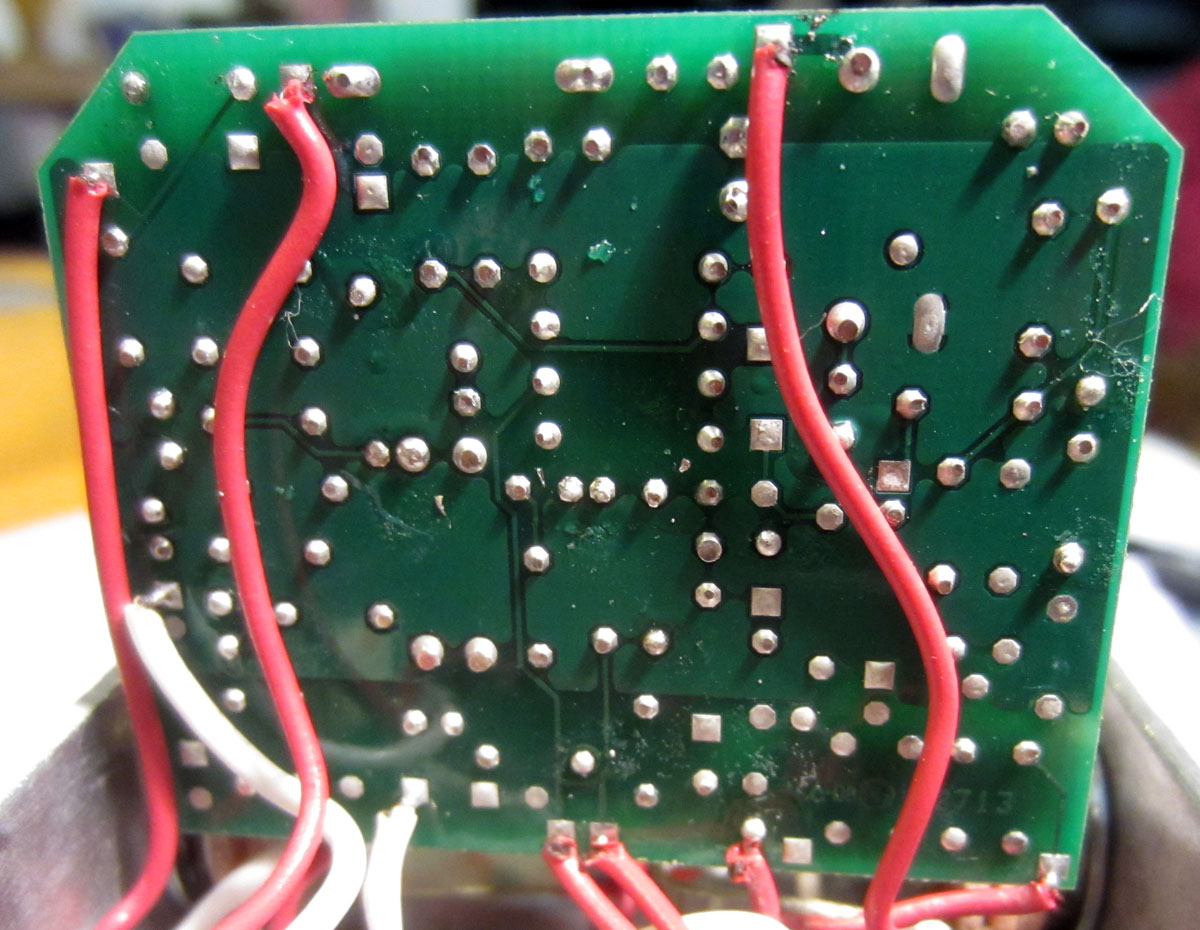
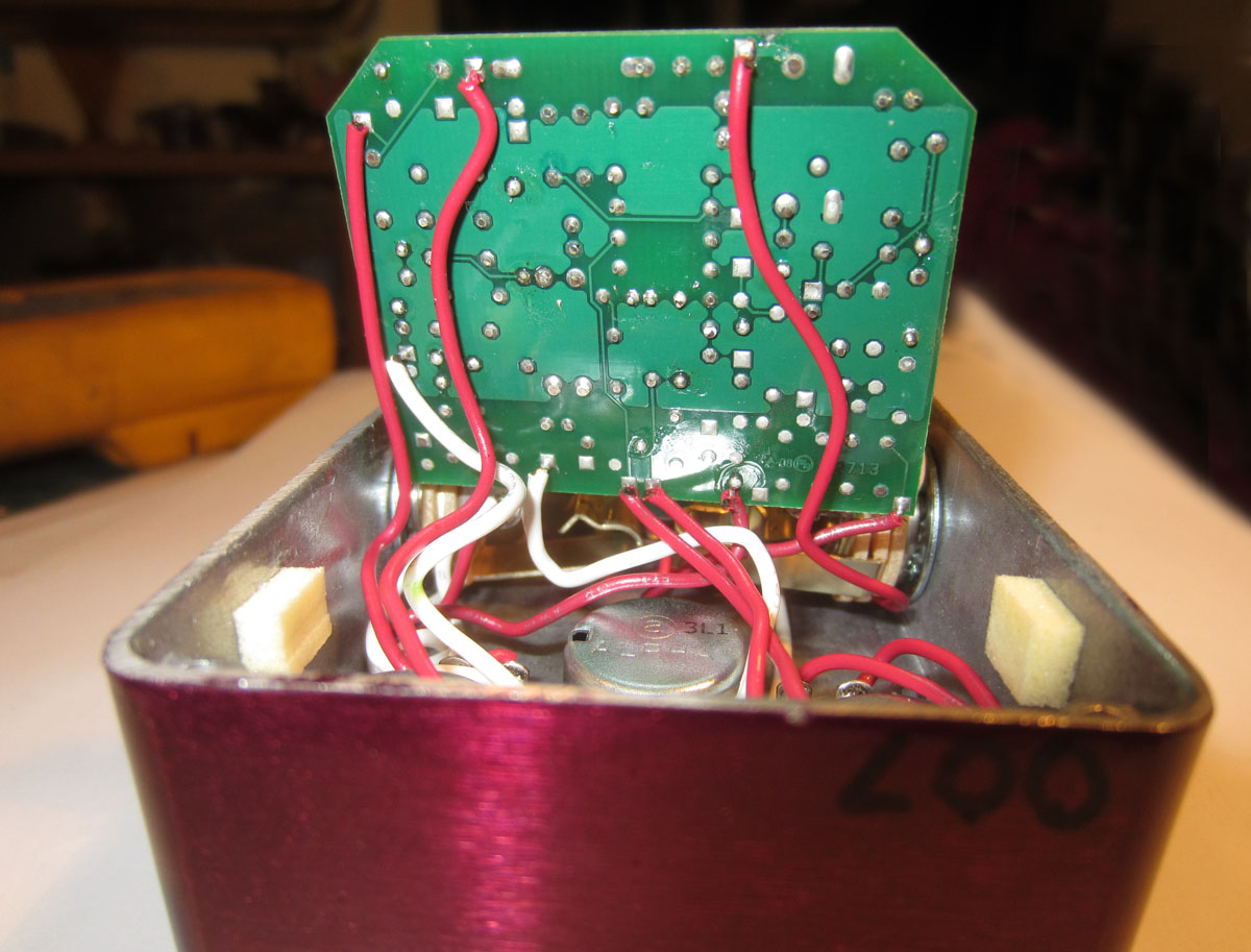
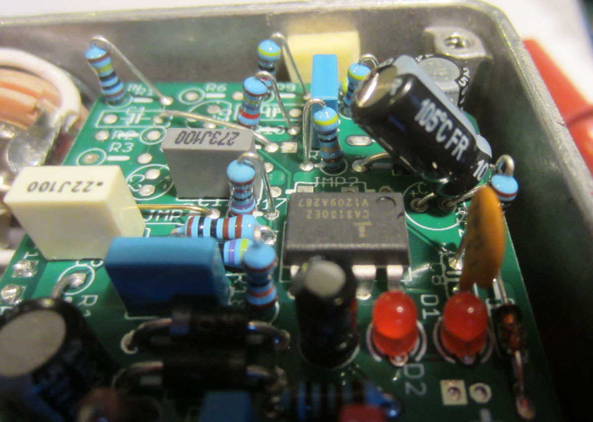
a friend of mine loaned me his Bearfoot Blueberry so I took a bunch of large pics of the guts. maybe these will help. and BTW it's using two 3mm red leds for the clippers and a CA3130EZ chip for the opamp.
         |
|
Administrator
|
That's awesome john. Thanks so much. I didn't know the bjfe was made on such a nice pcb. I figured it would have been gooped and parts being delabeled, like all the other effects I've seen made as bjfe.
|
|
Love these hires board photos. Some observations:
* All resistors are metal film 1% * All the box, ceramic caps are 5% tolerance (J) * I like the way he lays the radial electro cap on its side to save vertical space * Lots of standing components but that OK if it results in a more compact PCB For experimental builds, I'm OK with 5% carbon film resistors, but for "good" builds (PCBs, Klons etc.) I am using metal film resistors exclusively. Probably reduces noise a little... |
|
In reply to this post by rocket88
it's is actually the Bearfoot one. |
|
Administrator
|
After I posted that I kinda thought that it was the bearfoot one. John, have you had a chance to play with it? If so, what do you think of it? Also, I know you've had a chance to play a lot of effects over the years, have you played through a bjfe bbbod? If so, how does this compare?
Btw, I noticed that there are - few dale resistors, the ones that are brown without lines. I haven't seen those in a build before. |
Re: BJFE BlueBerry OD Creation - Circuit Help
|
Nice pics, thanks John.
I'd say the Bearfoot and BJFE pedals are similar if not identical. I like the Bearfoot one, anyway. Now that I think about it, the video example I posted earlier in this thread was of the Bearfoot, not the BJFE, so...  EDIT I'll look more closely at this later today and make a list of values. Then it'll just be to match components to schematic and get building 
Through all the worry and pain we move on
|
|
Administrator
|
Oh I know they're supposed to be similar, but since the bjfe one is so rare, i just wonder, since there's no demos of it or comparison between the two. I agree that I like the bearfoot one anyway, sooooo as long as we get the values I do have the layout.
 and this will be build immediately. and this will be build immediately.
|
Re: BJFE BlueBerry OD Creation - Circuit Help
|
Yeah man same here. I'll put all my other builds on hold for this one

Through all the worry and pain we move on
|
|
In reply to this post by rocket88
there is actually a demo comparison of the original BJFE and the bearfoot here: http://www.talkbass.com/threads/blueberry-bass-overdrive-bbbod-which-one.1087128/#post-16093671 I built a BBOD using the Madprofessor layout and then modded it to sound more like the Bearfoot one. AFAIK the BJFE's used green leds and an LM301 opamp whereas the Bearfoot uses red ones and a CA3130. |
Re: BJFE BlueBerry OD Creation - Circuit Help
|
cool!. i'm going to draw up and etch a PCB for that one.
|
Re: BJFE BlueBerry OD Creation - Circuit Help
|
Awesome man. If no one takes it on by Monday, I'll do a vero with the adjusted component values. I'm sure someone else will beat me to it though because I'm not home this weekend.
Shit I'm excited now 
Through all the worry and pain we move on
|
Re: BJFE BlueBerry OD Creation - Circuit Help
|
Oh and Rocket, if you're going to do a PCB layout, could you try your best to not have any standing axial components?
 I'm not too keen on soldering standing things, I hate it. I'm not too keen on soldering standing things, I hate it.
Through all the worry and pain we move on
|
|
Administrator
|
Haha, me do a pcb layout for it, I'm no where near being able to do that. I have the vero layout I made/posted, so I can easily change the parts to the right values. It will be done tonight.
 And shit, excited doesn't even say how happy I am about this one. |
Re: BJFE BlueBerry OD Creation - Circuit Help
|
Oh whoops, meant John. Saw him as you there

Speaking of PCB layouts, I have the Lite version of Eagle, and it's the most fucking confusing program I think I've ever used. I can't make heads or tails of the damn thing. Maybe I need more practice, but there isn't much intuitive about that program. I want to try out Mictester's Schmitt trigger switching system, so I might as well do this on PCB as long as I'm etching.
Through all the worry and pain we move on
|
|
Administrator
|
I agree about eagle. I tried it and it was a mess. I've etched some boards before, but it took a long time start to finish, and the traces never came out as nice as I wanted them. Then I stumbled onto vero, and I love it, and haven't looked back. I would do it again for something that couldn't be done on vero in a reasonable size.
And this me being john has got to end eventually. |
«
Return to Open Chat
|
1 view|%1 views
| Free forum by Nabble | Edit this page |

