First post - First pedal - First Problems!
123


123
First post - First pedal - First Problems!
|
Hello everyone,
My name is Olivier. I am 42 and I do love electronics and music. So a guitar overdrive as first electronic project could not be better. I started with the vemuram Jan Ray diagram. I spent a few (fun) hours building everything but I still have some questions regarding diagram. Hopefully someone can guide me. 1. 3 links= I have to connect row 1 with row 6. Row 6 with row 11 and row 5 to 8. Correct? 2. Gain 2 & 3 to Treble 1 & 2 = gain 2 to treble 1 and gain 3 to treble 2. Correct? 3. In the bitsbox kit, there are 4x 1N4148 Diode and 1x 1N5817 Schottky Diode. I used the Schottky for D5. correct? 4. In the kit there are ◦1x 47nF Polyester Film and ◦1x 47nF Polybox. On the diagram 2x 47u. Which one goes where? How can I read there positions on the diagram? 5. On the diagram, there is an orange cable to Bass 1 & 2 = connect 2 cables from the entry point on the PCB, 1 on Bass 1 + 1 on Bass 2? Thanks in advance for your help Olivier |
Re: First post - First pedal - First Problems!
|
hi Olivier!
welcome on board! on No1 and No3 you're correct. first i'll answer No2 and No5.No5 is correct as you described it but it's easier if you connect bass1 and bass2 lugs right on the potentiometer. take a cuted off leg of a resistor and link those 2 lugs.then from one of those 2 lugs, take just one wire and go to where bass1&2 is on the board. same on No2. connect gain2&3. then connect treble 1&2. then from gain2 or 3 (it doesn'e matter cause they're connected) take just one wire and go to treble 1&2. so you were wrong on that one.it's 2&3 to 1&2 not 2 to 1 and 3 to 2. No4 now. on the layout, is clear where you should put those 2x47nF caps. those are showed dark red. the 47uF (or 47μF.it's the same thing)are bigger polarized caps. those are the purple-blue ones on the layout. watch out for those cause you have to place them right (+&-). hope i helped. you can ask anything you want good luck! |
Re: First post - First pedal - First Problems!
|
Thanks for your prompt and clear answer.
100% clear but still one question thekit has ◦1x 47nF Polyester Film ◦1x 47nF Polybox I see the 2 47nF positions but I don t know where to put the box and where to put the film. Can I put then in any of the 2 positions? |
Re: First post - First pedal - First Problems!
|
Hi Olivier
Savvas has you well covered here. Regarding you cap dilemma... The type of cap is mostly irrelevant...its the value (and polarity) thats important. So you can put your caps wherever you like any way round as they don't have polarity (positive and negative side). The circular capacitors are electrolytic caps and they DO have polarity, indicated by the stripe down one side (denotes the negative leg). With these caps you MUST orientate correctly or they will fail. All the best |
Re: First post - First pedal - First Problems!
|
In reply to this post by odellicour
i've never had a problem. i use whatever i have wherever i need it. polyester or polybox.
ceramic thought might produce more noise( i think )in some circuits or in some places in some circuits. i'm not good on this thought. i think it's because of tolerance, temperature and staff like that...  but on this one it doesn't matter. put them in any position |
Re: First post - First pedal - First Problems!
|
To the "put them in any position" advice, I'll add "where they fit". If one way fits better than the other physically then do that.
Through all the worry and pain we move on
|
|
In reply to this post by odellicour
Hi Olivier, welcome.
I have had a look at the layout, and have an answer for you about the two different 47nF you have in the kit. You have been given a poly box cap, and a film cap for a reason: The 47nF poly box cap needs to be fitted in the position on the left side of the board (below the trim pot). The 47nF film cap needs to be fitted in it's position on the right hand side of the board. The reason for this is simple - most poly box caps have very short legs, and are a perfect fit across three rows on veroboard. Hence this cap goes on the left. Poly film caps have very long legs, which can be bent to fit across many rows - in this case across six rows. Electronically, there is no difference between the two, it is only a case of using the type of cap that best fits it's location. If you have already managed to solder them in the "wrong" place, do not worry, it won't make any difference to the performance of the circuit. Everything will work ok. I hope this helps. |
Re: First post - First pedal - First Problems!
|
Thanks guys, very helpful
So I corrected the Gain to Treble mistake I had put the poly on the left for soldering convenience so that one was ok. Everything was ok to me so I plugged my guiter into the pedal. First good point, the pedal is powered and the led works fine. The sounds goes through it when not engaged. Hélas when I switch it ON there is no sound at all :-( So I have failed something somewhere but where ... It is not going to be easy to find!!! |
|
It sounds like you have made an error on your switch wiring, which should not be too hard to find.
Use this wiring scheme: 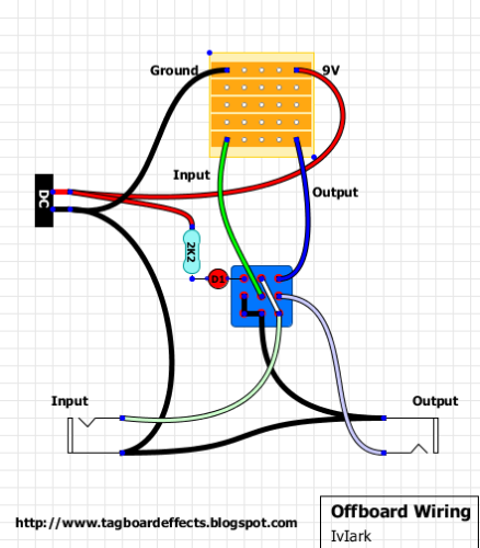 Just make sure that the "blades" on the switch are horizontal, not running vertical. |
Re: First post - First pedal - First Problems!
|
That's the one I used and the blades are in the right direction.
Attached some pics of my first "masterpiece"!!! If you see stg wrong ... 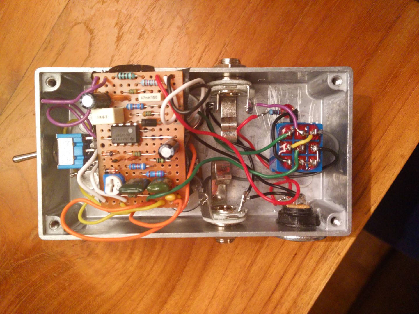 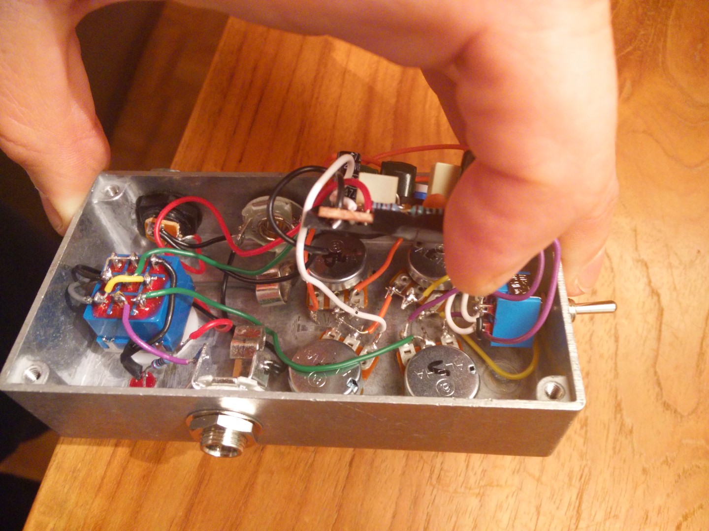 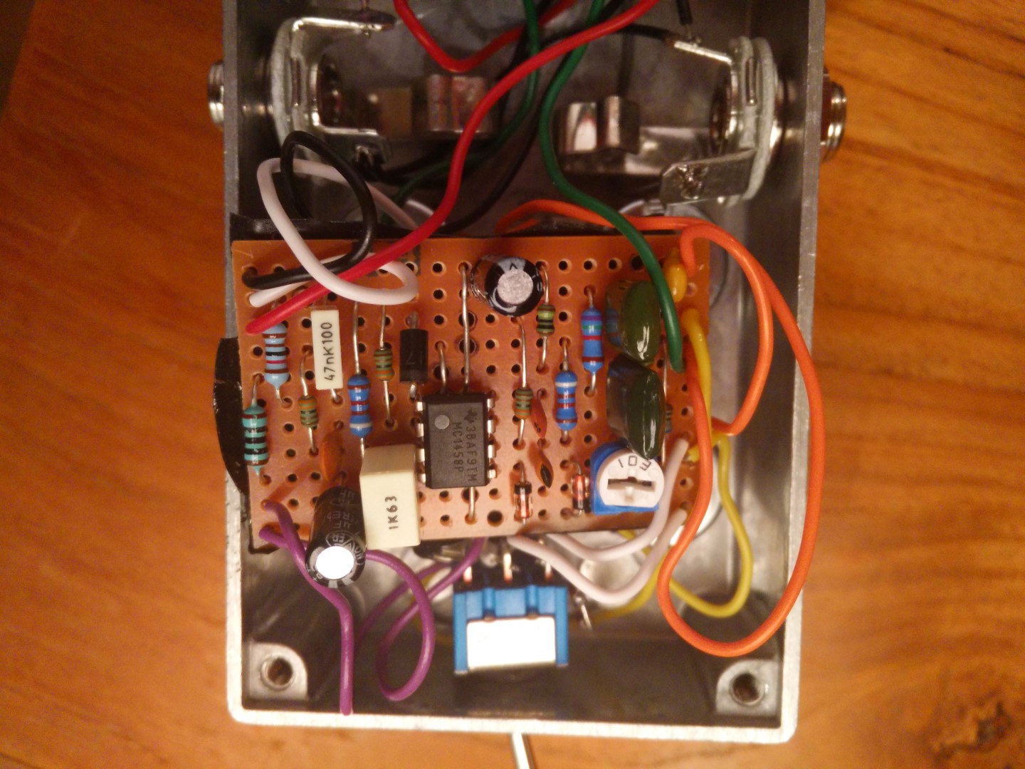 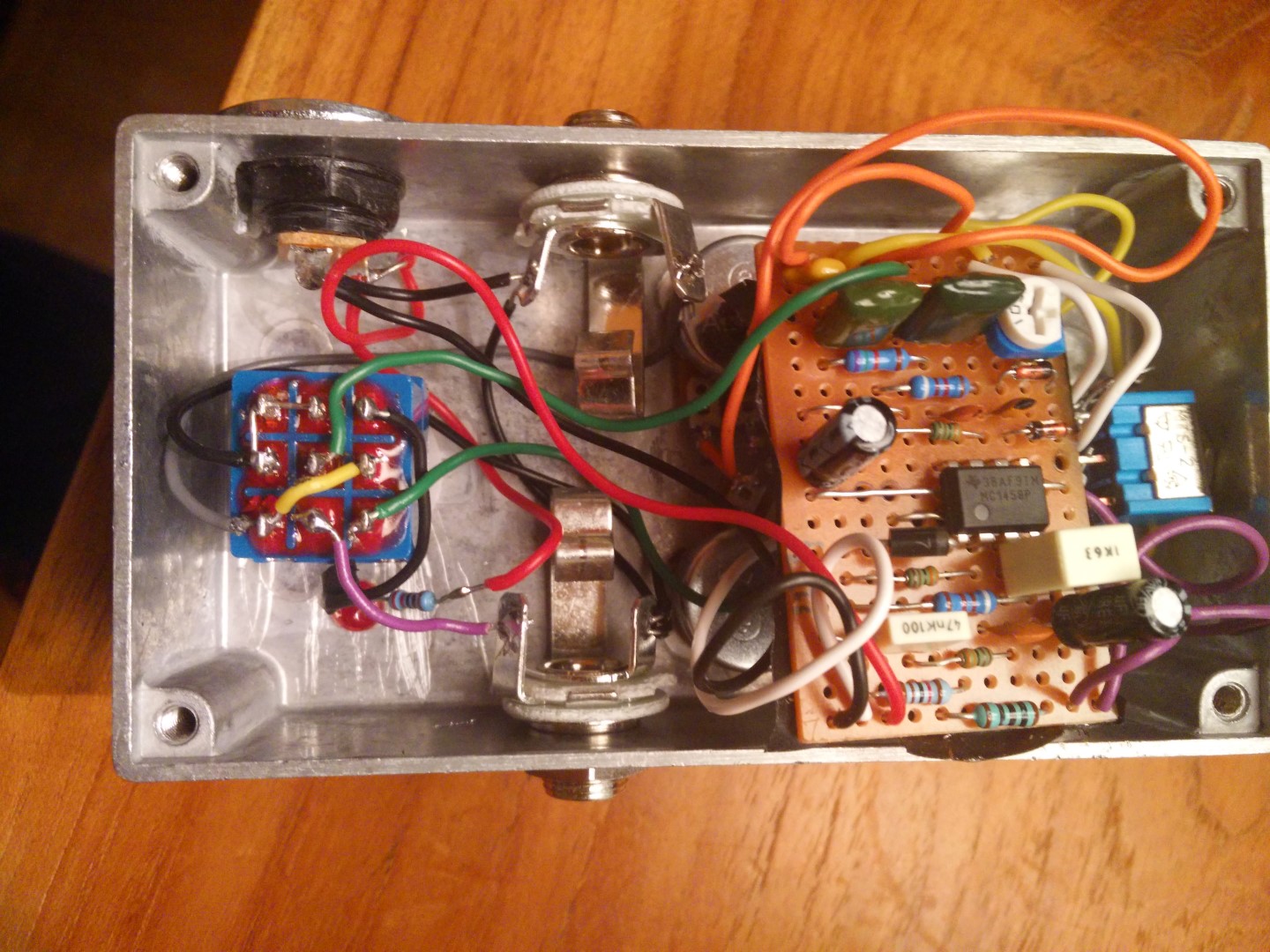
|
Re: First post - First pedal - First Problems!
|
Looks like your IC is upside down. The small circle denotes Pin 1. If you look at the layout you will see a shaded semi circle that also denotes Pin 1. And it's hard to tell but is that diode sharing a hole with an IC leg? Sent from my iPhone
|
Re: First post - First pedal - First Problems!
|
Where is the small circle on the IC ? Don t see it. Le dim. 27 sept. 2015 21:44, Ciaran Haslett [via Guitar FX Layouts] <[hidden email]> a écrit :
|
Re: First post - First pedal - First Problems!
|
Ah
The IC (integrated chip). Is the 8 legged black chip in the middle of your board. You can see a small circle on it. This tells you where Pin 1 of the chip is. And on the layout diagram from this site you can see a shaded semi circle that tells you which way to put the chip in...in this case you have put it in upside down. It will not work unless corrected (and hopefully it wasn't damaged). In future, you should try to use IC sockets. This way you do not solder the chip at all. You can swap in different ones to audition etc. And the diode I was talking about is the black 1Nxxxx one right next to your IC. Try taking the chip out and turning it around. Good luck |
|
In reply to this post by odellicour
Yes, Ciaran is correct. You have two mistakes.
#1. You need to turn your IC around. Hopefully it will still work. I would always use socket if I were you, as it is very easy to kill an IC by overheating it. You may want to replace it with a brand new one. I would be suprised if it survives being soldered in place, de-soldered, then soldered again the right way round. Sorry! #2. You need to de-solder the top leg of D5 from row 6, and re-solder it into row 7 (one row below the IC). |
Re: First post - First pedal - First Problems!
|
Thank you very much guys. I will order a socket and a new chip. Le dim. 27 sept. 2015 23:58, Beaker [via Guitar FX Layouts] <[hidden email]> a écrit : Yes, Ciaran is correct. You have two mistakes. |
Re: First post - First pedal - First Problems!
|
In reply to this post by Beaker
PS: I checked D5. It is at the right place but the leg is too long and very close to the IC. I will resolder it Le lun. 28 sept. 2015 07:36, Olivier Dellicour <[hidden email]> a écrit :
|
Re: First post - First pedal - First Problems!
|
you could also check that trick for the pots that don't have holes in their lugs.
http://tagboardeffects.blogspot.gr/2012/02/offboard-wiring.html cut a small piece of vero 2x5 and solder on that. that could save you some debugging time in the future. cheers! |
Re: First post - First pedal - First Problems!
|
For the socket, should I buy this one : http://www.bitsbox.co.uk/index.php?main_page=product_info&cPath=255_256&products_id=1931 or this one: http://www.bitsbox.co.uk/index.php?main_page=product_info&cPath=252&products_id=1886 2015-09-28 9:13 GMT+02:00 ξεναγος νεκροπολης [via Guitar FX Layouts] <[hidden email]>: you could also check that trick for the pots that don't have holes in their lugs. |
|
They`re exactly the same, first one is 12p for 1 second is £1.00 for 15. I`d go for the 15
If it wasn't for this website I would definitely have a life.
|
Re: First post - First pedal - First Problems!
|
12 pins VS 15 pins ? Le lun. 28 sept. 2015 12:23, dexxyy [via Guitar FX Layouts] <[hidden email]> a écrit : They`re exactly the same, first one is 12p for 1 second is £1.00 for 15. I`d go for the 15 |
«
Return to Open Chat
|
1 view|%1 views
| Free forum by Nabble | Edit this page |


