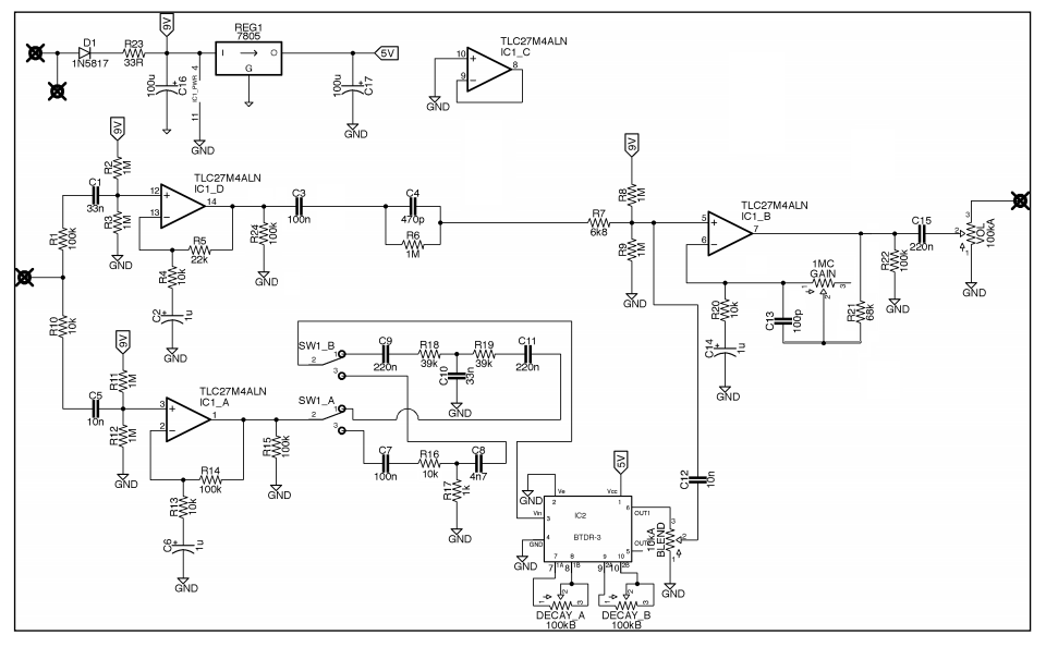
dba reverberation machine corrected schematic
123


123
dba reverberation machine corrected schematic
|
Hi, I posted a commend on 18 October 2018 (as unknown) in the dba reverberation machine vero build, in which i state that i track the high resolution photos posted by tabbycat here http://freestompboxes.org/viewtopic.php?f=7&p=254853#p254853 and i came up with a couple of differences/adds to the schematic provided by tabbycat, and so to the vero layout that Alex biuld.
Anthony Barratt replied to my comment and asked me to provide a schematic with my corrections in it. I know it's been a long since then but i finally managed to upload it. So here it is Anthony. The pedal works perfectly with these changes, much closer to the real thing than it was with Alex's vero. Please, if someone else followed my instructions and has something to mention i'll be glad to hear and discuss it. Here is the schematic:  |
|
Should this be considered as a "corrected" schematic or just a modded one? I would say if it was considered "corrected" it would be as the original, but here you have added decay pots on the belton brick which is not on the original.
Don't get me wrong, I appreciate your work cause I build the layout by Alex which works fine, but I also want it to be like the original. |
Re: dba reverberation machine corrected schematic
|
You are right aelling. I shouldnt have added the decay pots. I just corrected the differences i found after tracing the photos but i left by mistake all the other schematic as i downloaded it from web. Hold on a sec and i'll upload the right one
|
Re: dba reverberation machine corrected schematic
|
In reply to this post by aelling
So here it is

|
Re: dba reverberation machine corrected schematic
|
In reply to this post by aelling
Now regarding your question if it's modded or corrected. If you read my comment from 18 Oct 2018 in the Building topic, you'll clearly see that what i did was just tracing the high res pics that tabbycat posted here http://freestompboxes.org/viewtopic.php?f=7&p=254853#p254853 from the original unit. My motivation for doing that was the fact that i played my vero build (Alex's vero) side by side to the original and for sure there were too many differences. So i came back and start tracing the pics. I immidiately saw some difs especially around the gain pot circuit. I spoted all those difs, modded then my build according to them and the pedal after that was much much closer to the real one, let say about 98% or so... There's only one issue to my mods in addition to the real one. The R1 in the vero build, which in the schematic is labeled R16 and is for sure 100K in the real one, sound better if 10K than 100K...that makes me believe that there must be some extra difference that i didn't spot in my tracing or, the fact that i used in my build TL074 than the TLC27M4AIN, is what it makes the 10K sound better that the 100K.
I am here to help you more if you like and if i can! |
|
In reply to this post by maragosspiros
Thank you very much, as I said I build Alex' layout but would rather have it as the original so time to dig that out and go over it. |
|
This post was updated on .
In reply to this post by maragosspiros
Fantastic! Thanks for taking the time to upload this, much appreciated!
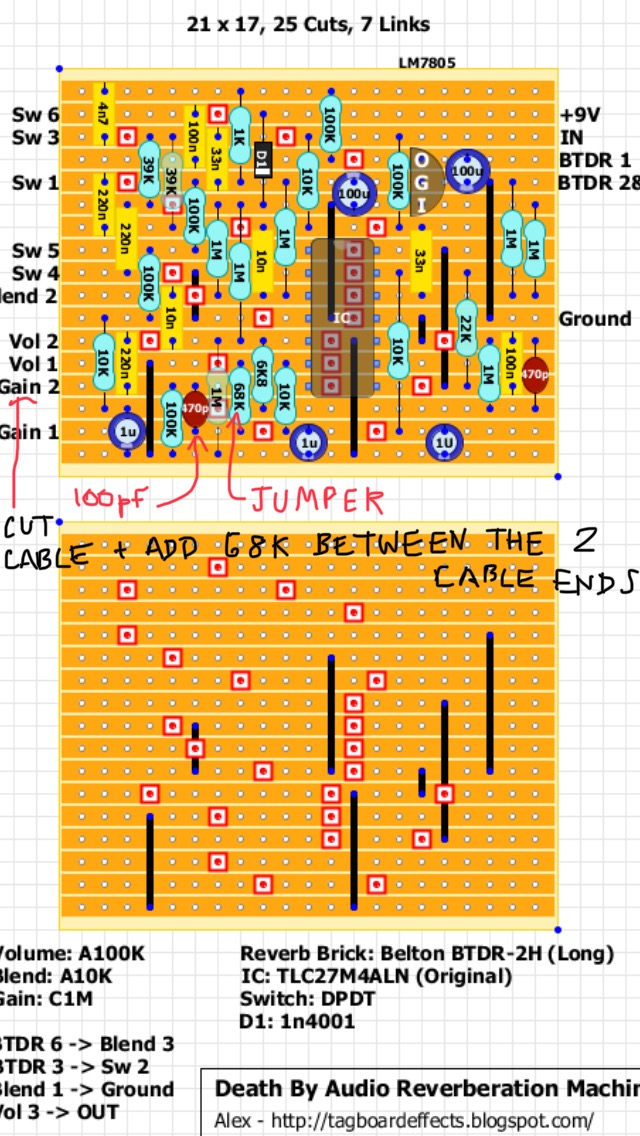
I think this is how you can fix the vero layout - great if someone can give this the once-over. Remember the 100k resistor at the top in the middle should be your 1-10k, depending on how loud you want the sunshine circuit. Cheers. (Anthony) 
|
|
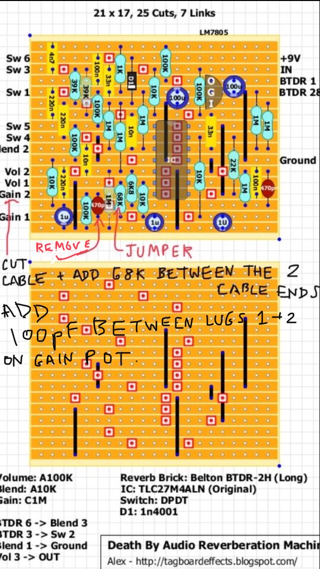
That won't do it I'm afraid, now only the 100pF and the 68K connects to Gain 2, on the layout Gain 2 still connects to pin 7 so there will need to be a cut between them, but once you do that the 220nF and 100K no longer connects to pin 7 and they still connect to Gain 2.
You could solder the 100pF straight onto the gain pot, as you figured jumper the 68K resistor on the board and solder one side of the 68K to Gain 2 lug and a wire from the other side to the Gain 2 on the board. I think that should do it, I'll pull mine out and test it. |
Did this to mine and it works, of course I didn't test it out before I did it so I don't know how it compares to before. I also added the 100K resistor from pin 14 to ground and swapped the 0-10K resistor to 100K, believe it or not I only had a 4.7K in there, the 100K was definitely way better. I also found out that the bright/dark switch only affects the wet reverb signal (hence the reason why 100K was better here), also that the dark setting is better for short(er) decays, bright setting is better for long(er) ones. Another thing I don't remember was how much gain this has, I dunno know if that was fixed with these new findings but it's an overdrive/distortion now. KUDOS maragosspiros  for going over this and finding these corrections. for going over this and finding these corrections.
|
Re: dba reverberation machine corrected schematic
|
Hi aelling, tell me please, which IC are u using? TL074 or a subtitute of it, or TLC27M4AIN? If you confirm the second one, it explains i guess the 100k in R1 as the original one instead the 10k i used combined with TL074..
|
|
I used a TLC274CN.
|
Re: dba reverberation machine corrected schematic
|
Ok, i'll have to check it out then! Thanks for fast reply!
|
|
I got it from tayda, there's a datasheet there
https://www.taydaelectronics.com/tlc274-quad-operational-amplifier-precision-pdip-14-tlc274cn.html |
Re: dba reverberation machine corrected schematic
|
What i meant was that i will check the resistor value combined with TLC274...right now i have in pedal TL074 with 10k. I will try a TLC274 with 100k and believe me, i really want that to succeed...and that because in the real pedal, there is a 100k in that position as i already mentioned, but my combination above is that close to the original sound that it's a bit confusing to me..
|
|
In reply to this post by aelling
Nice!
|
|
In reply to this post by aelling
I've tried to find some demos of a clone that was made from the layout on the main site, and what Adam gets from his build is how I remember mine before I made the corrections, it was just not quite like an original. But with the corrections made it now sounds like an original |
|
So just to be sure, do this and everything is ok?

|
|
Yes, I also added the 100K resistor from IC1 pin 14 to ground.
|
|
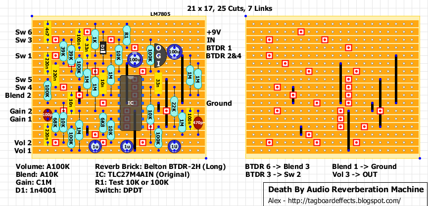
This should work (different layout):

|
|
In reply to this post by maragosspiros
Okay, never mind the 100K resistor thing, my dumb ass didn't realise one of the wires had broken off the darK/bright switch, once I fixed it I too got the results everyone else was getting, nearly no tails on the bright side unless the Blend pot was all the way on. I swapped out the 100K for a 10K and it works alot better now, so I dunno if that is just the difference between the ICs or what. |
«
Return to Debugging
|
1 view|%1 views
| Free forum by Nabble | Edit this page |


