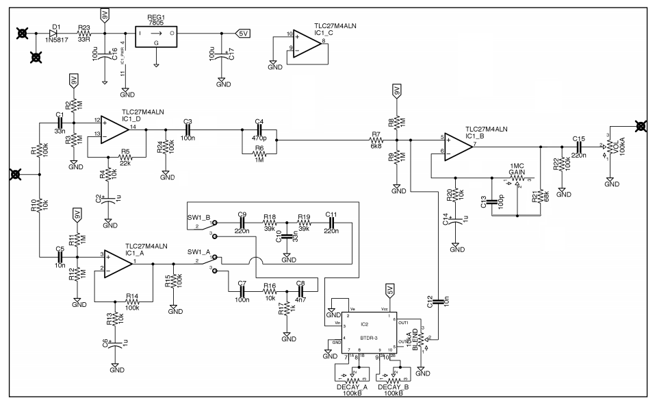
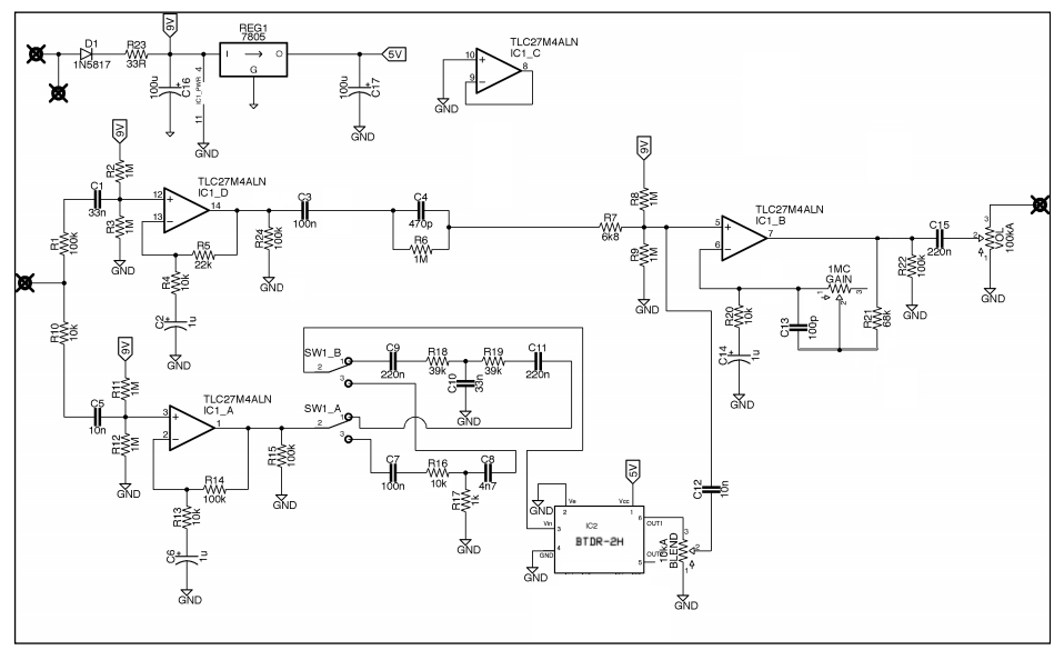
dba reverberation machine corrected schematic

123

123
dba reverberation machine corrected schematic

|
Re: dba reverberation machine corrected schematic
|
|
Re: dba reverberation machine corrected schematic
|
|
Re: dba reverberation machine corrected schematic
|
|
Re: dba reverberation machine corrected schematic
|
|
Re: dba reverberation machine corrected schematic
|
|

Re: dba reverberation machine corrected schematic
|
|
Re: dba reverberation machine corrected schematic
|
|
Re: dba reverberation machine corrected schematic
|
|
 for going over this and finding these corrections.
Re: dba reverberation machine corrected schematic
|
|
Re: dba reverberation machine corrected schematic
|
|
Re: dba reverberation machine corrected schematic
|
|
Re: dba reverberation machine corrected schematic
|
|
Re: dba reverberation machine corrected schematic
|
|
Re: dba reverberation machine corrected schematic
|
|
Re: dba reverberation machine corrected schematic
|
|
Re: dba reverberation machine corrected schematic
|
|
Re: dba reverberation machine corrected schematic
|
|
Re: dba reverberation machine corrected schematic
|
|
Re: dba reverberation machine corrected schematic
|
|
| Free forum by Nabble | Edit this page |